Molecular Combing of DNA: Methods and Applications
Received 11 December 2012; Accepted 15 January 2013
Journal of Self-Assembly and Molecular Electronics, Vol. 1, 125–148.
doi: 10.13052/same2245-4551.116
Copyright © 2013 River Publishers. All rights reserved.
Zeinab Esmail Nazari*, Leonid Gurevich*
- Institute of Physics and Nanotechnology, Aalborg University, 9220 Aalborg, Denmark
- *Corresponding author: lg@nano.aau.dk
Abstract
First proposed in 1994, molecular combing of DNA is a technique that allows adsorption and alignment of DNA on the surface with no need for prior modification of the molecule. Since then, many variations of the original method have been devised and used in a wide range of applications from genomic studies to nanoelectronics. While molecular combing has been applied in a variety of DNA-related studies, no comprehensive review has been published on different combing methods proposed so far. In this review, the underlying mechanisms of molecular combing of DNA are described followed by discussion of the main methods in molecular combing as well as its major applications in nanotechnology.
Keywords
- Molecular combing of DNA
- DNA stretching
- AFM
1. Introduction
While most of our electronics devices currently rely on silicon technology, the Moor’s law predicts that we are approaching its limits [1, 2], implying that we are still in search for new ideas. Nature is a perfect source of inspiration, in particular, from the perspective of complex and reliable machinery at nanoscale it employs. For instance, the multi-complex protein machinery responsible for DNA replication (also known as replisome) is a nanomachine that polymerizes DNA at an amazing rate of up to 1000 nucleotides per second and makes less than one mistake per 109 nucleotide incorporations [3]. If we aim to achieve that level of complexity and precision in our future nanotechnology devices, probably the best way would be to bring our technology closer to that of nature. The very first step to achieve this would be to harvest the potential of the existing biological building blocks by incorporating them into our nanodevices and develop hybrid structures containing both organic and inorganic parts.
In this context, and for many reasons, DNA has been the center of attention in nanotechnology research, from genomic and biomedical studies [4, 5] to development of nanomachines and nanocircuits [6]. However, many investigations and manipulations are not possible on DNA molecule in its natural coiled structure. From this perspective, strategies that enable us to immobilize and straightening DNA on a solid substrate would be of great value since they open many possibilities for nanotechnology, for instance, fabrication of hybrid structures benefiting, on one hand, from unique features of self-assembly, recognition, and self-replication of DNA [7–9] and, on the other hand, from state-of-the-art fabrication procedures developed for inorganic materials. In order to achieve this aim, numerous methods have been introduced for aligning DNA molecules on solid surfaces using different approaches which involve stretching DNA using optical or magnetic tweezers [10], spin stretching [11, 12], or stretching inside nanofluidic channels [13]. Most of these techniques for stretching DNA require further modification of DNA extremities through biochemical reactions to anchor DNA to a functionalized substrate, e.g., via sticky ends or biotin functionalization [14]. An interesting approach for aligning DNA on solid surfaces is molecular combing of DNA, which is a reliable method for immobilization and stretching of DNA without the need for any prior modification to DNA extremities [15]. This technique was first introduced by Bensimon et al. in 1994 who also coined the name “molecular combing” [16]. It has been extensively used since then and many different protocols have been devised with the idea of combing: anchoring hairs at one end and using a force to comb them!
Combing can be defined as a procedure in which – under certain conditions of pH and ionic strength – DNA molecules are attached, at one or both ends, to the surface and subsequently aligned by the force applied at the air/water interface. Molecular combing offers a number of advantages over common stretching methods: as mentioned earlier, it allows stretching of DNA without the need to modify the ends of DNA, it is suitable for stretching a large number of DNA molecules as well as very long strands of DNA molecules, such as genomic DNA, and it is a facile and convenient procedure with reasonable reproducibility.
In the simplest form of this technique, a droplet of DNA solution is deposited on a hydrophobic surface. At proper values of pH and ionic strength, DNA molecules slightly unwind at the ends and expose the hydrophobic core (formed by stacked hydrophobic bases), which can attach to the surface via hydrophobic interactions. Then, moving the liquid-air interface along the substrate will drag the hydrated part of DNA molecules and result in stretching of the molecules with one or both ends attached to the surface. While this is the basic idea, different combing techniques use different strategies to induce the moving interface. The force applied by the receding meniscus is typically estimated ∼400 pN, which is two orders of magnitude greater than the entropic forces keeping DNA in its coil structure (and comparable to the bond strength between biotin and streptavidin), yet not enough to detach DNA from the surface [15, 16]. This procedure results in formation of uniformly stretched and parallel arrays of DNA molecules on the substrate. Movement of the meniscus can be induced by many different techniques such as by pulling a substrate out of solution containing DNA or evaporating a droplet as will be discussed below.
Before discussing various combing procedures, an important point should be made. When the group lead by David (physicist) and Aaron (molecular neurobiologist) Bensimon, who contributed significantly to different aspects of combing, introduced molecular combing in 1994 [16], the technique relied on hydrophobic interactions of partially melted DNA ends with the surface. Different hydrophobic surfaces have been employed for combing: glass or silicon surfaces modified with hydrophobic silanes [17], polystyrene surfaces [18], polymethylmetacrylat (PMMA) surfaces [5], polydimethylsiloxane (PDMS) [19], etc. However, the term “combing” has also been applied to the experiments performed on charged surfaces ranging from clean glass [20] to the surfaces modified with positive coatings including amino terminated groups such as polylysin and polyhystidine [20], 3-aminopropyltrimethoxysilane (APTMS)-coated [21] and 3-aminopropyltriethoxysilane (APTES)-coated surfaces [20], where electro-static interaction of the DNA molecule with the surface plays important role. It should be noted that typically the use of charged substrates results in unspecific electrostatic interaction of DNA mid-segments with the surface, while the hydrophobic surfaces at proper values of pH and ionic strength ensure more specific adsorption of DNA from extremities via relatively strong hydrophobic interactions.
Later on, with attempts to achieve further control over positioning of DNA molecules, the methods were introduced that involved a combination of combing with lithographic approaches [18, 22]. This has resulted in development of methods with more capabilities and, therefore, a wider range of potential applications in nanotechnology and biomedicine. In this context, in addition to aligning DNA molecules on the substrate, controllable and reproducible patterning of arrays of aligned DNA molecules with a desired distance becomes possible [22].
The primary objective of this review is to focus on the main experimental aspects of molecular combing of DNA, including the choice of surface, pH and ionic strength of the solution as well as to discuss various techniques useful for positioning and aligning DNA molecules. While the applications of combing in genomics, DNA replication and cancer studies have been recently reviewed by John Herrik and Aaron Bensimon [23], no comprehensive review has been published on molecular combing of DNA as a technique with a variety of applications from biomedicine to nanoelectronics. Here we will attempt to cover most of significant achievements in nanoscience that involved application of combing technique. To meet this end, the underlying mechanism of combing will be described first, followed by the discussion of different techniques in molecular combing. The third part of the review will focus on main applications of combing in nanotechnology and biomedicine.
2. Mechanism
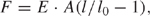
Combing occurs in three main steps: adsorption of the ends of floating coiled DNA molecules to a substrate, stretching DNA by the forces exerted by the receding meniscus, followed by relaxation of the deposited DNA on the substrate to its final length. A simple procedure for combing DNA is presented in Figure 1.
As discussed before, under certain pH and ionic strength conditions, DNA is partially melted at the ends. Upon unwinding of DNA at the ends, the hydrophobic core of DNA double helix is exposed and is readily attracted to the hydrophobic surfaces. When the moving air-water interface is passing along the solid substrate, the coiled DNA is stretched with one or both ends attached to the surface. At very low pH values (typically, below pH 4), DNA tends to denature along the length of the molecule resulting in non-specific binding to the surface at several random points along the DNA length. This leads to low and non-uniform DNA stretching. On the other hand, at physiological pH values, the unwinding at the extremities is inhibited and most molecules leave the surface. Although the optimal pH range depends on the nature of the surface, structure of DNA extremities (e.g., presence of sticky ends) and ionic strength, typically, the optimal unwinding of DNA extremities is achieved in a narrow range of pH between 5 to 5.6 [24].
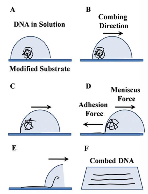
Figure 1 Schematic representation of basic steps in molecular combing of DNA. Under certain conditions of pH and ionic strength, DNA is partially melted at the extremities and then adsorbed to the surface by the ends. When the moving meniscus is formed, the adhesion force between DNA and the surface dominates the meniscus force, resulting in random coiled DNA being stretched, while the meniscus passes along the surface.
Combing process is governed by the surface tension forces existing at the air-water interface. During movement of the meniscus, the receding air-water interface leaves the bound DNA molecules fully extended behind and stretched on the dry substrate. This means that the surface tension of the air-water interface at each point exhibits a force on the DNA on that point. This force, F , is proportional to the surface tension γ at the air-water interface and the wetted diameter d of the DNA molecule: F = γπd. In this equation we assume that first, the DNA chain is completely wet by the water and second, the DNA chain is stretched perpendicular to the air-water interface. Taking γ= 7 × 10⁻² N/m for air/water interface, and d = 2.2 nm for B-DNA, the force acting on DNA can be estimated as 400 pN. This force is two orders of magnitude greater than the entropic forces that maintain DNA in its native random coil structure, yet smaller than the force required to break the covalent bonds in DNA backbone, which is of the order of 1 nN [16]. As was established by Smith et al. [25], when the force acting on DNA increases from the entropic range to a level from 6 to 60 pN, DNA starts to behave as an elastic rod with a stretch modulus of E · A ∼ 1000 pN where E is the Young modulus of B-DNA and A its effective cross-sectional area [26]. In this force range, the force vs. extension curve follows Hook’s law:
where E = 1.1 × 10⁸ N/m2 is the Young modulus of DNA molecules, A = 3.8×10⁻¹⁸ m2 is the cross-sectional area of a molecule, l0 is the contour length of DNA, and l/ l0 is the relative extension. When the force reaches approximately 70 pN, DNA suddenly yields and overstretches up to 1.7-fold its B-form crystallographic length [25]. This corresponds to a transition from the B-form DNA to an “overstretched” DNA that believed to be a “ladder” composed of two parallel ssDNA strands. At even higher forces the dsDNA melts into two parallel ssDNA strands, which can be further stressed without breaking up to 800 pN [27, 28]. Unless there are nicks in the DNA strands, the overstretching transition is reversible and the DNA will return to its B-form upon releasing the stress. On the other hand, the melting transition is loading rate dependent and is not expected to occur during fast DNA stretching characteristic for combing process [19].
As illustrated in Figure 1, when the moving meniscus is formed, there is a constant stretching force parallel to the direction of combing, which acts on DNA molecules in the vicinity of the contact line. If the adhesion force between DNA and the surface is sufficiently high and dominates the meniscus force, the DNA undergoes transition from coil to the stretched form [19, 29]. This condition puts a lower limit on the value of the adhesion force holding the extremities of DNA.
The last stage of combing process corresponds to the DNA molecule relaxing on solid surface after passage of the meniscus. The DNA undergoes relaxation towards its B-form until the stress in DNA is balanced by its interaction with the surface (van der Waals, hydrophobic, etc.). Typically this corresponds to the relative extension of 1.2 times, although higher values are sometimes reported [21].
It has been shown that the density of combed molecules on the surface is not heavily affected by increasing the DNA concentration in solution; rather, it is strongly dependent on the radius of gyration RG1 of the DNA molecule in solution, which essentially limits how closely DNA molecules can approach each other [18]. Although this size can be affected by ionic strength of the solution [19], in order to significantly increase the density of combed DNA, it might be necessary to repeat combing procedure for a number of times [18].
Studies suggest that combing is an irreversible process, which means that if the substrates with combed DNA has been dried sufficiently, the already-combed DNA molecules remain stretched on and attached to the surface upon rehydration and it is possible to perform combing repeatedly [15, 18]. The physics and theoretical aspect of DNA elastisicity and stretching is beyond the aim of this review and the readers are encouraged to follow the extensive discussions by Bensimon and his team [15, 26, 30].
3. Basic Combing Techniques
3.1. The Original Bensimon Method
In the original Bensimon method, a droplet containing DNA solution (pH = 5.5) was deposited on a silanized coverslip covered with another glass and left to evaporate. The movement of the air/water interface occurred upon evaporation of the solution lead to DNA stretched on the silanized glass perpendicular to the meniscus (Figure 2) [15, 20]. In 2004, Zheng et al. used the same method for combing of DNA on cetyltrimethyl ammonium bromide (CTAB)-coated surface instead of silane-coated surface. CTAB is a cationic surfactant which is also used as a germicidal chemical due to its ability to bind to DNA. The stretched DNA molecules were reported to be 30% longer compared to the contour length of λ-DNA at pH = 5.5 [31].
3.2. Moving Coverslip
A variation of Bensimon’s method was used three years later by Yokota et al. based on mechanical moving of the meniscus by a droplet-spreading apparatus (Figure 2). After incubation of DNA solution which is spread on a silanized glass slide, the coverslip is dragged across the slide surface using a motor-driven apparatus at a constant speed [32].
$$$1 RG – the half average size of the coiled DNA molecule in solution – is a widely used measure for the characterization of the configuration of DNA as a polymer. It measures the root-mean square distance of the collection of segments from their common center of mass.

Figure 2 Left: The original method – proposed by Bensimon – for molecular combing of DNA. During incubation, DNA molecules become attached to silanized glass by their extremities. When the upper coverslip is removed, molecules are uniformly stretched and aligned by the receding air-water meniscus (left). Reprinted with permission from [20]. © 1997 Elsevier. Right: Variation of Bensimon’s method based on moving of the meniscus by a motor-driven apparatus. Reprinted with permission from [32]. © 1997 Oxford University Press.
3.3. Dynamic Combing
In 1997, Michalet et al. reported dynamic molecular combing for stretching total genomic DNA based on Langmuir-Blodgett deposition technique [33]. In this method, after preparation of trichlorosilane-coated surfaces, the substrates were incubated in the solution of either yeast or human genomic DNA (pH = 5.5) for 5 min, after which the surface was pulled out of the solution at a constant speed, as shown in Figure 3. When the cover slip was pulled out of the solution, the anchoring points moved upward together with the surface, while the fixed horizontal meniscus exerted a constant downward vertical force. An important advantage of dynamic combing procedure over the original Bensimon method is that the use of large volumes (2–20 ml) of buffer solution in this method allows better control of pH of DNA solution compared to small volumes of 5 μL. This is particularly important considering the narrow pH range in which molecular combing is observed.
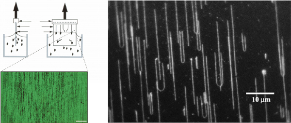
Figure 3 Dynamic combing employed for stretching large quantities of genomic DNA. Left: A silanized coverslip is incubated in DNA solution in order to allow adsorption of DNA molecules to the surface. The coverslip is then pulled out of the solution in vertical direction leaving up to several hundred genomic DNA molecules behind. Reprinted with permission from [33]. © 1997 American Association for the Advancement of Science. Right: Fluorescence microscopy image of the DNA strands aligned using the dynamic molecular combing method. Reprinted with permission from [34]. © 2003 Elsevier.
3.4. Combing with a Moving Droplet
Probably the simplest method for combing DNA on the surface is stretching by gas flow. In this method, a droplet containing DNA solution is deposited and incubated on modified substrate and the sample is blown dried with nitrogen gas. If the gas is blown in appropriate direction and angle (∼45° relative to the surface), DNA molecules will be stretched. The method was first proposed in 1998 [35] and new variations of the method were used later [36]. The disadvantage of this method is that the actual parameters of the gas flow strongly depend on the distance between the surface and the gas source and may vary between the experiments.
Combing DNA using gravitational force is a common method too [37, 38]. In this approach, the substrate is tilted approximately 80° with respect to its horizontal position and a droplet of DNA solution is placed at the upper edge of the substrate. The droplet slides down as a result of gravitational force and the moving air-water interface stretches DNA molecules [19].
3.5. Combing by Droplet Suction
In 2002, Nakao et al. proposed a procedure for generating highly-aligned long strands of DNA [39]. The cover slips were coated with poly(vinylcarbazole) (PVCz) and polyphenazasiline (PPhenaz) polymers via spin-coating. A droplet of DNA solution was then deposited and incubated on polymer-coated surfaces. Combing of DNA was performed by sucking the droplet up by a pipette which induced the movement of the air/water interface and subsequent alignment of DNA along the central direction of the droplet. It was also possible to comb DNA on other substrates such as silicon wafers and graphite (Figure 4) [39].
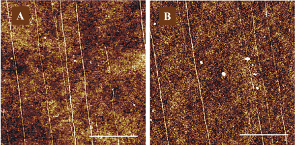
Figure 4 AFM topography of DNA stretched on PPhenaz-coated glass (A) and PVCz-coated glass using pipette sucking method. The white bar denotes 1.0 μm (B). Reprinted with permission from [39]. © 2002 American Chemical Society.
Later on in 2006, the same procedure was used for combing DNA on a surface of a di-block copolymer; polystyrene-b-poly(methyl methacrylate) (PS-b-PMMA) [40].
4. Complex Combing Methods
While initially the combing techniques were designed to simply achieve DNA stretching on non-patterned, flat surfaces mostly for applications in genomic analysis, application of DNA in molecular electronics requires better control over the orientation; position and distance between combed molecules. These methods generally involve a combination of combing with micro- and nano-fabrication techniques such as lithographic patterning, Dip Pen Lithography (DPN) and Transfer Printing (PT).
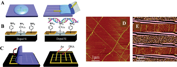
Figure 5 Combing DNA on Si substrate (A) Molecular combing was used in order to achieve aligned DNA strands using a piece of filter paper. (B) Si substrate was modified by APTES producing an amino-terminated surface to anchor DNA molecules. (C) Combed DNA molecules are transferred from PDMS to the Si chip by contact printing. (D) DNA crossed structures were prepared with layer-by-layer contact printing. (E) DNA combed across electrodes on Si substrates. Reprinted with permission from [41]. © 2005 American Chemical Society.
4.1. PDMS Printing
In 2005, Zhang et al reported a combination of molecular combing and transfer printing of λ-DNA, in which a piece of filter paper was used to control the movement of the meniscus [41]. This technique involved incubation of a drop of λ-DNA solution (pH = 8) on PDMS substrate followed by adsorption of the solution at a constant rate with a piece of filter paper, as shown in Figure 5. Afterwards, the combed DNA strands were transferred from the PDMS sheets onto APTES-treated Si surface by contact printing. In this way, using layer-by-layer contact printing, it was possible to form aligned patterns of DNA strands on Si surface, e.g., crossing each other or aligned across micro electrodes. The PDMS printing method has the advantage of uniformity of the stretched molecules, simplicity, reproducibility and the fact that the speed of the meniscus is controlled by the pore size of the filter paper [41].
4.2. Combing across Nanoelectrodes
In a recent approach, the authors have developed a method for combing DNA on Si substrates bearing lithographically-patterned Pt/Cr nanoelectrodes [17]. In this method, Si substrates were silanized using gas phase deposition of N-Octyldimethylchlorosilane. Compared to the commonly used N-Octadecyltriclorosilane, the use of N-Octyldimethylchlorosilane resulted in a molecularly-smooth surface with an average contact angle of ∼90° which made it easy to drag the droplet on the modified surface. After deposition and incubation of DNA on silane-modified substrate, the capillary forces between the droplet and the plastic pipette tip was used to gently drag the droplet out of the surface. The movement of the air/water interface results in highly-ordered alignment of DNA molecules that were stretched up to 160% of their original crystallographic length. The average percentage of stretching was calculated as 122%. Additionally, using the relatively large meniscus force produced by this method, it was also possible to comb more rigid derivatives of DNA such as DNA-peptide nanowires [17, 42]. These structures were composed of a DNA core, coated with a peripheral layer of self-assembled short cationic peptides [43–46]. While combing of these structures was not efficient using other available techniques, it was possible to comb these nanowires to their full length, as shown in Figure 6C.
The technique was also used for combing across silicon substrates with nano-fabricated platinum electrodes. In that case, it was possible to achieve 700 nm-long stretches of dsDNA across nanoelectrodes [17].
4.3. Combing on E-Beam Patterned Polystyrene Templates
In 2001, Klein et al. developed a new technique based on stretching of DNA between micro-fabricated polystyrene lines. Polystyrene readily forms cross links between chains under e-beam irradiation and can be used as negative e-beam resist. Since cross-linked chains are less soluble in organic solvents compared to the initial material, and DNA binds equally well to cross-linked polystyrene, it was possible to control the binding regions on the substrate and achieve positioning of combed DNA molecules [18]. The Si/SiO2 substrates with e-beam patterned polystyrene layer were then dipped into a solution of λ-DNA for approximately 1 min to allow hydrophobic interactions between DNA extremities and polystyrene lines. Next, the silicon substrate was pulled out with a constant speed which resulted in stretching of DNA across and between the polystyrene lines (Figure 7) [18].
The advantage of this method is that it is possible to achieve control over positioning of DNA arrays on the substrate. This offers a potential advantage in studies on DNA nanowires and DNA-based nanoscale devices. Additionally, the technique offers a good possibility of large-scale automated fabrication of DNA nanowires for applications in either DNA electronic or population-based genetic diseases and genomic screening.
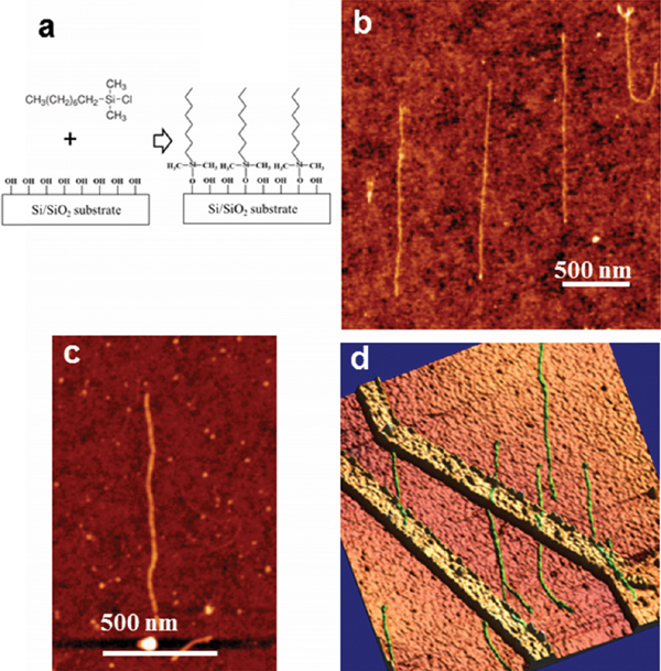
Figure 6 Combing DNA molecules using pipette tip method (a). Schematics of surface modification with Octyldimethylchlorosilane. The molecules can form only a single bond to the surface, therefore producing smooth monolayers. (b) combed dsDNA molecules on the surface, average height ∼0.7 nm (c) combed peptide-coated DNA, average height 3.4 nm (d) dsDNA molecules combed across nano-fabricated electrodes (2 × 2 μm scan area) [17].
4.4. Combing on Dip Pen Lithography (DPN) Templates
A combination of molecular combing and Dip Pen Lithography (DPN) is another example of how one could achieve more control over DNA molecule by using a combination of combing with other procedures. In the method described by Nyamjav and Ivanisevic in 2003, different patterns with the size down to 50 nm were “inked” using contact-mode AFM scanning of poly(allylamine hydrochloride) (PAH)-coated tip on Si substrate [47]. Molecular combing of DNA was then performed on PAH-patterned templates and DNA strands were combed along the PAH layer. Using this method, surface templates with well-defined regions of positive and negative charges has been demonstrated that could be used for guided deposition and combing of DNA together with other biomolecules [47]. Two years later, the same team extended this technique to achieve templating of DNA with magnetic nanoparticles. In this technique the DNA molecules were templated by Fe3O4 nanoparticles prior to combing on PAH layer. In this way, it was possible to achieve magnetic nanowires positioned and aligned on the substrate [48].
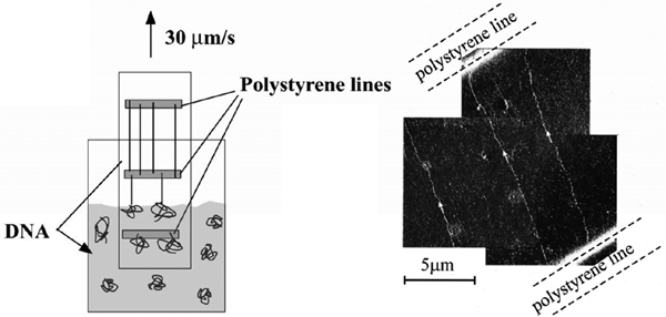
Figure 7 Combing across polystyrene lines microfabricated on Si/SiO2 substrates. The substrate is dipped into DNA solution and then retracted at a constant speed. DNA molecules bind to the polystyrene lines and are stretched by the meniscus force (left). Amplitude AFM image of DNA stretched between patterned polystyrene lines (right). Reprinted with permission from [18]. © 2001, American Institute of Physics.
4.5. Transfer Printing of Combed DNA
In 2003, Gad et al. used the combing procedure described in Section 3.5, for stretching λ-DNA on PDMS sheets, followed by transfer-printing of DNA from PDMS to mica substrate [49]. DNA molecules were initially combed on PDMS by both methods of pipette-sucking [49] and pulling up the substrate out of DNA solution [50], and then were micro-contact printed on freshly cleaved mica resulting in stretched DNA patterns on mica surface. The method allows creation of complex patterns by repeated printing; however, the exact position and length of DNA molecules could not be controlled.
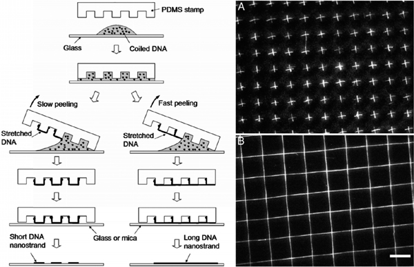
Figure 8 Procedure for transfer-printing of DNA. After incubation of DNA on a glass cover-slip, a PDMS stamp is pressed on the solution, and peeled off the surface from one end with the other end remaining in contact with the glass surface (left). It results in generation of ordered arrays of either short (A, slow peeling) or long (B, fast peeling) patterns of stretched DNA on mica or glass substrate. Reprinted with permission from [22]. © 2005 National Academy of Sciences, USA.
Two years later, Guan and Lee combined molecular combing with lithographic approaches in order to generate ordered alignments of DNA on substrate [22]. In their method, the droplet of DNA solution was first incubated on a glass coverslip, and a PDMS stamp was then placed on top of the solution. After manual peeling from one end, the stamp was transferred on a new solid surface by direct contact printing which literally resulted in short (peeling with low-speed) or long (peeling with high-speed) arrays of DNA on the surface. The advantage of this technique is that more complex patterns could be produced by additional steps of printing (Figure 8) [22].
Later on, more techniques were developed based on using capillary assembly in combination with soft-lithography in order to achieve ordered arrays of isolated DNA strands. Some of these techniques resulted in stretching of DNA up to 160% of its contour length [21]. We would mention in particular the procedures involving UV-light for end-specific binding of DNA to the patterned thin, spin-coated aminoterpolymer (ATP) film [51].
5. Parameters Affecting Combing Efficacy
As discussed above, the extent of stretching depends on a number of combing parameters such as the choice of substrate, buffer, surface functionalization method, etc. In addition, in nanoelectronic applications, the control over the position and orientation of DNA strands on the substrate is of great importance.
It has been shown that change in pH has a significant effect on both density of DNA molecules adsorbed on the surface and the extent of stretching. The optimal pH for combing DNA on a surface is highly dependent on the nature of the surface used. In general, most results, if not all of them [52], agree that for hydrophobic surfaces, pH values in the range from 5–5.5 are ideal for adsorption of DNA to the substrates [17, 20, 31]. At very low pH values DNA bases are largely protonated (e.g., pH = 3 and 0.1 M salt content corresponds to 50% protonation) [20]. This protonation weakens hydrogen bonds holding the strands together, decreases the melting temperature, and partially exposes the hydrophobic core of DNA helix hence causing nonspecific adsorption of DNA to the surface. However, with the increase in pH value, the melting occurs less frequently, so at pH 5.5, only the extremities of DNA are sufficiently hydrophobic to bind to a hydrophobic surface [20].
It has also been reported that the efficacy of combing is dependent on the ionic strength of the buffer used. For surfaces such as PDMS, increasing the concentration of NaCl in the buffer up to 100 mM, resulted in better stretching of DNA where the number of stretched DNA molecules reached a maximum [19]. In general, the ionic strength of the solution controls screening of the DNA backbone and substrate charges and as such can affect a number of parameters important for combing, including melting temperature and melting extent at the extremities, gyration radius of DNA coils, as well as DNA interaction with the surface.
The choice of surface functionalization method is also important. For instance, in silanization procedure, the nature of the silane used defines the extent of hydrophobicity of the substrate which directly affects the strength of interaction of DNA with the substrate. While the use of silanes have been a common choice for preparation of hydrophobic surfaces, some studies showed that a number of polymers containing π-conjugation units (such as polyphenazasiline, PPhenaz and poly(vinylcarbazole), PVCz) also result in highly-aligned DNA molecules [39]. In general, the degree of stretching is usually higher in hydrophobic rather than hydrophilic surfaces, due to strong and specific adsorption of DNA and higher meniscus forces (>100 pN) [20, 31]. Effect of hydrophobicity of the substrate on combing quality is discussed in [52].
The speed of the moving meniscus also affects the quality of combing. This could be controlled by either using different sizes of a filter paper or a motor-driven apparatus [18], as discussed above. Generally, meniscus speed in the range of 300–500 μm/s is acceptable [33, 41], but studies suggest that it could be also as high as 5 mm/s when using a filter paper with a pore size of 11 μm to absorb the DNA solution [41]. It has also been shown that increase in the adsorption speed and hence the receding meniscus speed, results in decrease in the density of DNA. However, significant reduction in meniscus speed (down to 250 μm/s) also decreased the density of stretched DNA [17, 41]. In addition, both the direction of blow drying and the angle at which the nitrogen gas is blown to the surface are important. The best results are achieved when the direction of gas flow has a tilt angle of 45° from that of the surfaces. Blowing at a large angle (parallel with the surface) causes DNA molecules to fly out of the surface, while blowing at too small an angle (perpendicular to the surface) would not stretch DNA molecules in a single direction [35]. The extent of stretching is affected by the length of DNA but is sequence-independent. In addition, the concentration of DNA as well as the incubation time of DNA needs to be optimized.
It should also be noted that the density of molecules stretched on the substrates does not depend on the DNA concentration; rather, it is related to the radius of gyration RG of the DNA molecule in solution. Therefore, the best way to increase the density of combed DNA molecules is probably to repeat the combing procedure few times until the desired density is achieved [18].
A comprehensive study of the parameters that affect the efficiency of DNA combing could be found in [29].
6. Applications
Most interestingly, molecular combing of DNA is used as a tool in many fields of science as diverse as physics, biology, and medicine. These applications fall into one of these categories:
6.1. A Tool in Genomic Studies
In fact, the early advances in DNA molecular combing were exclusive to high-resolution studies of chromosomal DNA molecules and studying genetic rearrangements. The first genetic disease diagnosed with the help of combing was previously-undetectable micro-deletions in the TSC2 gene responsible for the disease tuberous sclerosis [23, 33]. Soon after, combing was adapted for many more applications such as detection of other genetic disorders and cancer. For instance, alterations in BRCA1 and BRCA2 are responsible for the majority of breast cancers; however, most previous PCR-based methods for detection of these alterations were not capable of detection of large rearrangements in genome. The use of molecular combing of DNA in such studies was significantly helpful in overcoming this problem. For instance, Gad et al. studied large rearrangements in BRCA1 using a combination of combing with a system of four-color bar coding. The color bar code method was able to detect micro-deletions on the order of 10 kb in a variety of BRCA cell lines from patients with breast cancer [53].
Fluorescence in situ Hybridization (FISH) is a cytogenetic technique used for detection of specific DNA sequences on chromosomes. In this technique, fluorescently labeled probes are used to hybridize to the desired sequences on chromosome. Fluorescence microscopy can then be used to visualize the fluorescent signals emitted by the fluorescent probe on the chromosome [5, 54]. Dynamic molecular combing has been a common choice for combing of DNA, with the possibility to comb total genomic DNA into a high density array of well-separated molecules (typically 50–100 diploid human genomes with lengths between 200–600 kb) [33]. After combing, regions of interest are visualized and characterized by fluorescence microscopy. Combing of DNA is also used in fiber-FISH in order to stretch large amounts of DNA (bacterial and yeast expression vectors or even whole genomes) on silanized glass for high-resolution detection of genes [54]. It is also possible to determine the ordering, orientation and distance between genes, as well as the existence of certain genomic rearrangements (e.g. deletions) [55].
The main advantage of molecular combing in genomic studies is the possibility to comb high concentrations of total genomic DNA in conditions preserving it from excessive shearing. For instance, it is possible to prepare high density of combed fibers of total human genome up to hundreds of long fragments (longer than several hundred kilo-bases) per cover slip [33]. Moreover, it is possible to prepare a very large number of identical substrates at the same time [5].
Application of combing technique in genetics gradually evolved to a method for studying dynamics of the replication of the genome [38, 56–59]. A comprehensive review on application of molecular combing in genomic studies can be found in [23].
6.2. Nanoelectronics
Application of DNA as a building block in future nanoelectronic devices is a charming idea. One of the main challenges in design and development of nanocircuits is inter-element wiring and positioning of nanodevices at nano-scale [60]. In this context, DNA is an attractive candidate due to self-assembly and recognition features which are unique to this molecule [7–9]. Taking advantage of these properties, it is possible to design procedures for controlled wiring of nanocircuits using DNA nanowires with adhesive ends. In addition, fabrication of multi terminal junction devices by crossing nanowires would be possible using branched DNA junctions (Holiday junctions) [61, 62]. Based on these reasons, and even though the electrical conductivity of DNA has been a subject of strong debates in last decade [63–71], DNA is still a unique candidate as a potential nanowire and a subject of many ongoing investigations [72]. In addition to normal dsDNA, modified forms of DNA including M-DNA (a complex of B-DNA with divalent metal ions Co2+, Ni2+ and Zn2+) [73], metal-coated DNA [74, 75], guanine quadruplexes G4-DNA [84], and DNA-peptide wires [42] have also been discussed as future nanowires.
Molecular combing of DNA plays an important role in such experiments since all these conductivity measurements primarily require proper stretching of DNA across electrodes. Therefore, combing method has been used as a common choice of a convenient yet effective method with no need for any prior modification to DNA [37, 63, 76, 77]. In some cases, combing of DNA has been used in combination with other lithographic techniques [51] or in conductivity measurement of overstretched DNA molecules [78]. Molecular combing has also been used to comb DNA derivatives such as DNA-peptide conjugates [44–46, 79] across nanoelectrodes for either analyzing DNA-protein interaction [80] or conductivity measurements [42].
As mentioned earlier, DNA-templated nanowires have been a subject of many studies in the last decade. The reason is that the molecular recognition and self-assembly properties of DNA make it a suitable potential template to organize and interconnect assemblies of nanoparticles on surfaces [81]. DNA-templated nanowires consist of DNA as the template and either metallic or semi-conductive nanoparticles as the coating layer. Such nanomaterials are excellent candidates for future nanoelectronics due to the fact that they possess structural advantages of DNA as a nanowire (self-assembly and recognition) together with the desired conductivity of metallic or semi-conductive particles.
The preparation of arrays of DNA-templated nanowires also include the use of combing technique for immobilization and stretching of DNA prior to assembly of nanoparticles on DNA template. For instance, Nakao et al. developed a method for ordered assembly of gold nanoparticles (Au-NPs) along DNA molecules [81]. Molecular combing has been also used in combination with dip pen lithography in order to stretch DNA molecules pre-templated with Fe3O4 magnetic nanoparticles [48].
In a more interesting approach, Keren et al. used combing of DNA to achieve DNA-templated nanowires in a system of nano-bio-lithography where desired sites on DNA are masked via homologous recombination by RecA protein, while other parts are coated with metallic nanoparticles in order to generate molecularly accurate DNA-templated junctions [82]. In a more recent approach, the same team used molecular combing technique as part of the fabrication procedure for DNA-templated nanofield effect transistors [83].
7. Conclusions
The emergence of new methods for nano-scale investigation and manipulation is very promising. Among these methods, molecular combing of DNA has shown promise in bridging between organic and inorganic elements. The large body of literature and the many experiments that involve combing is the best indication of the reliability and efficiency of this method. Besides biomedical applications in cytogenetics and cancer genomics such as screening of genome for cancer and genetic diseases due to genomic rearrangements, the application of molecular combing has allowed many state-of-the-art advances in new areas of research in nanophysics and nanoelectronics. Development of DNA-templated nanowires for future nanoelectronics, single molecule lithography and nanofabrication of DNA-based nanodevices are good examples that were discussed in this review. The simplicity of the combing technique and its broad range of application on one hand and rich physics of DNA deformation involved in the combing process on the other hand warrant that this review will not stay complete or comprehensive for long, but hopefully will rather encourage the use of this elegant technique.
Acknowledgements
The authors gratefully acknowledge support by EU COST action MP0802 “Self-assembled guanosine structures for molecular electronic devices” and grants from the Obel Family Foundation.
References
[1] L. B. Kish Phys. Lett. A, 305, 144–149 (2002).
[2] M. Lundstrom Science, 299, 210–211 (2003).
[3] A. M. van Oijen, J. J. Loparo Annu. Rev. Biophys., 39, 429–448 (2010).
[4] A. Stewart Mol. Med. Today, 4, 2 (1998).
[5] J. Herrick, A. Bensimon Chromosome Res., 7, 409–423 (1999).
[6] F. Zamora, M. P. Amo-Ochoa, P. J. Sanz Miguel, O. Castillo Inorg. Chim. Acta., 362, 691–706 (2009).
[7] C. M. Niemeyer Curr. Opin. Chem. Biol., 4, 609–618 (2004).
[8] R. Chhabra, J. Sharma, Y. Liu, S. Rinker, H. Yan Adv. Drug Deliver. Rev., 62, 617–625 (2010).
[9] E. Farjami, L. Clima, K. Gothelf, E. E. Ferapontova Anal. Chem., 83, 1594–1602 (2011).
[10] C. G. Baumann, V. A. Bloomfield, S. B. Smith, C. Bustamante, M. D. Wang, S. M. Block Biophys. J., 78, 1965–1978 (2000).
[11] H. Yokota, J. Sunwoo, M. Sarikaya, G. van den Engh, R. Aebersold Anal. Chem., 71, 4418–4422 (1999).
[12] L. M. Bellan, J. D. Cross, E. A. Strychalski, J. Moran-Mirabal, H. G. Craighead Nano Lett., 6, 2526–2530 (2006).
[13] L. J. Guo, X. Cheng, C.-F. Chou Nano Lett., 4, 69–73 (2004).
[14] D. J. Doolittle, G. Muller, H. E. Scribner Chem. Toxic., 25, 399–405 (1987).
[15] D. Bensimon, A. J. Simon, V. Croquette, A. Bensimon Phys. Rev. Lett., 74, 4754–4757 (1995).
[16] A. Bensimon, A. Simon, A. Chiffaudel, V. Croquette, F. Heslot, D. Bensimon Science, 265, 2096–2097 (1994).
[17] Z. Esmail Nazari, L. Gurevich Beilstein J. Nanotechnol., in press (2013).
[18] D. C. G. Klein, L. Gurevich, J. W. Janssen, L. P. Kouwenhoven, J. D. Carbeck, L. L. Sohn Appl. Phys. Lett., 78, 2396–2398 (2001).
[19] A. Benke, M. Mertig, W. Pompe Nanotechnology, 22, 035304 (2011).
[20] J. F. Allemand, D. Bensimon, L. Jullien, A. Bensimon, V. Croquette Biophys. J., 73, 2064–2070 (1997).
[21] A. Cerf, C. Thibault, M. Geneviève, C. Vieu Microelectron. Eng., 86, 1419–1423 (2009).
[22] J. Guan, L. J. Lee PNAS, 102, 18321–18325 (2005).
[23] J. Herrick, A. Bensimon Methods Mol. Biol., 521, 71–101 (2009).
[24] J. Herrick, A. Bensimon Biochimie, 81, 859–871 (1999).
[25] S. B. Smith, Y. Cui, C. Bustamante Science, 271, 795–799 (1996).
[26] T. Strick, J. Allemand, V. Croquette, D. Bensimon Prog. Biophys. Mol. Biol., 74, 115– 140 (2000).
[27] M. Rief, H. Clausen-Schaumann, H. E. Gaub Nat. Struct. Biol., 6, 346–349 (1999).
[28] H. Clausen-Schaumann, M. Rief, C. Tolksdorf, H. E. Gaub Biophys. J., 78, 1997–2007 (2000).
[29] J. H. Kim, W.-X. Shi, R. G. Larson Langmuir, 23, 755–764 (2007).
[30] T. R. Strick, J.-F. Allemand, D. Bensimon, V. Croquette Biophys. J., 74, 2016–2028 (1998).
[31] H.-Z. Zheng, D.-W. Pang, Z.-X. Lu, Z.-L. Zhang, Z.-X. Xie Biophys. Chem., 112, 27–33 (2004).
[32] H. Yokota, F. Johnson, H. Lu, R. M. Robinson, A. M. Belu, M. D. Garrison, B. D. Ratner, B. J. Trask, D. L. Miller Nucleic Acids Res., 25, 1064–1070 (1997).
[33] X. Michalet, R. Ekong, F. Fougerousse, S. Rousseaux, C. Schurra, N. Hornigold, M. van Slegtenhorst, J. Wolfe, S. Povey, J. S. Beckmann, A. Bensimon Science, 277, 1518–1523 (1997).
[34] K. J. Kwak, S. Yoda, M. Fujihira Appl. Surf. Sci., 210, 73–78 (2003).
[35] J. Li, C. Bai, C. Wang, C. Zhu, Z. Lin, Q. Li, E. Cao Nucleic Acids Res., 26, 4785–4786 (1998).
[36] Z. Deng, C. Mao Nano Lett., 3, 1545–1548 (2003).
[37] T. Heim, T. Mélin, D. Deresmes, D. Vuillaume Appl. Phys. Lett., 85, 2637–2639 (2004).
[38] M. Oshige, K. Yamaguchi, S.-I. Matsuura, H. Kurita, A. Mizuno, S. Katsura Anal. Biochem., 400, 145–147 (2010).
[39] H. Nakao, H. Hayashi, T. Yoshino, S. Sugiyama, K. Otobe, T. Ohtani Nano Lett., 2, 475–479 (2002).
[40] G. Liu, J. Zhao Langmuir, 22, 2923–2926 (2006).
[41] J. Zhang, Y. Ma, S. Stachura, H. He Langmuir, 21, 4180–4184 (2005).
[42] Z. Esmail Nazari, L. Gurevich In preparation.
[43] C.-H. Hsu, C. Chen, M.-L. Jou, A. Y.-L. Lee, Y.-C. Lin, Y.-P. Yu, W.-T. Huang, S.-H. Wu Nucleic Acids Res., 33, 4053–4064 (2005).
[44] W. Zhang, J. P. Bond, C. F. Anderson, T. M. Lohman, M. T. Record PNAS, 93, 2511– 2516 (1996).
[45] L. Gurevich, T. W. Poulsen, O. Z. Andersen, N. L. Kildeby, P. Fojan J. Nanosci. Nanotechnol., 10, 1–5 (2010).
[46] P. Fojan, K. Jensen, L. Gurevich IEEE Xplore 2011, DOI 10.1109/Wireless-vitae.2011.5940906.
[47] D. Nyamjav, A. Ivanisevic Adv. Mater., 15, 1805–1809 (2003).
[48] D. Nyamjav, A. Ivanisevic Biomaterials, 26, 2749–2757 (2005).
[49] H. Nakao, M. Gad, S. Sugiyama, K. Otobe, T. Ohtani J. Am. Chem. Soc., 125, 7162– 7163 (2003).
[50] M. Gad, S. Sugiyama, T. Ohtani J. Biomol. Struct. Dyn., 21, 387–393 (2003).
[51] J. Opitz, F. Braun, R. Seidel, W. Pompe, B. Voit, M. Mertig Nanotechnology, 15, 717– 723 (2004).
[52] H. Kudo, K. Suga, M. Fujihira Colloids Surf. A., 313, 651–654 (2008).
[53] S. Gad, A. Aurias, N. Puget, A. Mairal, C. Schurra, M. Montagna, S. Pages, V. Caux, S. Mazoyer, A. Bensimon, D. Stoppa-lyonnet Genes, Chromosomes Cancer, 31, 75–84 (2001).
[54] A. V. de Barros, T. S. Sczepanski, J. Cabrero, J. P. M. Camacho, M. R. Vicari, R. F. Artoni Aquaculture, 322, 47–50 (2011).
[55] S. Caburet, C. Conti, A. Bensimon Trends Biotechnol., 20, 344–350 (2002).
[56] D. M. Czajkowsky, J. Liu, J. L. Hamlin, Z. Shao J. Mol. Biol., 375, 12–19 (2008).
[57] J. N. Bianco, J. Poli, J. Saksouk, J. Bacal, M. J. Silva, K. Yoshida, Y.-L. Lin, H. Tourrière, A. Lengronne, P. Pasero Methods, 57, 149–157 (2012).
[58] K. Koutroumpas, J. Lygeros Automatica, 47, 1156–1164 (2011).
[59] R. Lebofsky, R. Heilig, M. Sonnleitner, J. Weissenbach, A. Bensimon Mol. Biol. Cell., 17, 5337–5345 (2006).
[60] L. Fu, L. Cao, Y. Liu, D. Zhu Adv. Colloid Interface Sci., 111, 133–157 (2004).
[61] T. H. Labean, H. Li Nano Today, 2, 26–35 (2007).
[62] H. Li, J. D. Carter, T. H. LaBean Materials Today, 12, 24–32 (2009).
[63] A. J. Storm, J. van Noort, S. de Vries, C. Dekker Appl. Phys. Lett., 79, 3881–3883 (2001).
[64] C. Gómez-Navarro, F. Moreno-Herrero, P. J. de Pablo, J. Colchero, J. Gómez-Herrero, A. M. Baró PNAS, 99, 8484–8487 (2002).
[65] P. J. de Pablo, F. Moreno-Herrero, J. Colchero, J. Gómez Herrero, P. Herrero, A. M. Baró, P. Ordejón, J. M. Soler, E. Artacho Phys. Rev. Lett., 85, 4992–4995 (2000).
[66] K. Iguchi Int. J. Mod. Phys. B, 17, 2565–2578 (2003).
[67] H.-W. Fink, C. Schönenberger Nature, 398, 407–410 (1999).
[68] O. Legrand, D. C^ ote, U. Bockelmann Phys. Rev. E, 73, 0319251–6 (2006).
[69] L. Cai, H. Tabata, T. Kawai Appl. Phys. Lett., 77, 3105–3106 (2000).
[70] Y. Okahata, T. Kobayashi, H. Nakayama, K. Tanaka Supramol. Sci., 5, 317–320 (1998).
[71] A. Y. Kasumov, M. Kociak, S. Guéron, B. Reulet, V. T. Volkov, D. V Klinov, H. Bouchiat Science, 291, 280–282 (2001).
[72] M. Taniguchi, T. Kawai Physica E, 33, 1–12 (2006).
[73] F. Moreno-Herrero, P. Herrero, J. Colchero, C. Gómez-Navarro, J. Gómez-Herrero, A. M. Baró Nanotechnology, 14, 128–133 (2003).
[74] H. Yang, K. L. Metera, H. F. Sleiman Coord. Chem. Rev., 254, 2403–2415 (2010).
[75] A. D. Chepelianskii, D. Klinov, A. Kasumov, S. Guéron, O. Pietrement, S. Lyonnais, H. Bouchiat New J. Phys., 13, 063046 (2011).
[76] M. Bockrath, N. Markovic, A. Shepard, M. Tinkham, L. Gurevich, L. P. Kouwenhoven, M. W. Wu, L. L. Sohn Nano Lett., 2, 187–190 (2002).
[77] L. Cai, H. Tabata, T. Kawai Nanotechnology, 12, 211–216 (2001).
[78] P. Maragakis, R. L. Barnett, E. Kaxiras, M. Elstner, T. Frauenheim Phys. Rev. B, 66, 241104–1–4 (2002).
[79] C.-H. Hsu, C. Chen, M.-L. Jou, A. Y.-L. Lee, Y.-C. Lin, Y.-P. Yu, W.-T. Huang, S.-H. Wu Nucleic Acids Res., 33, 4053–4064 (2005).
[80] H. Yokota, D. A. Nickerson, B. J. Trask, G. van den Engh, M. Hirst, I. Sadowski, R. Aebersold Anal. Biochem., 264, 158–164 (1998).
[81] H. Nakao, H. Shiigi, Y. Yamamoto, S. Tokonami, T. Nagaoka, S. Sugiyama, T. Ohtani Nano Lett., 3, 1391–1394 (2003).
[82] K. Keren, M. Krueger, R. Gilad, G. Ben-Yoseph, U. Sivan, E. Braun Science, 297, 72–75 (2002).
[83] K. Keren, R. S. Berman, E. Buchstab, U. Sivan, E. Braun Science, 302, 1380–1382 (2003).
[84] H. Cohen, T. Sapir, N. Borovok, T. Molotsky, R. Di Felice, A. B. Kotlyar, D. Porath Nano Letters 7, 981–986 (2007).
Biographies

Zeinab E. Nazari received her Master’s degree in Pharmacy from Mashhad University of Medical Sciences, Iran in 2007. In 2012, she received her second Master’s degree in Nanobiotechnology from Institute of Physics and Nanotechnology, Aalborg University, Denmark. Presently, Zeinab works as research assistant in Leonid Gurevich group. Her research is focused on conductivity measurements of DNA-based nanomaterials.

Leonid Gurevich received his Ph.D. in Physics at the Institute of Solid State Physics (Chernogolovka, Russia) in 1994. He initially worked on high-Tc superconductors but during his postdoc stay at Delft University of Technology became excited about nanotechnology and the possibility of charge transport through a single molecule. Since 2005 he is an Associate Professor at Aalborg University. His research interests focus on molecular electronics, biosensors and nanofabrication.