Analysis of a Pre-Stressed Quadcopter Propeller Using Finite element Approach
Faraz Ahmad*, Pushpendra Kumar and Pravin P. Patil
Department of Mechanical Engineering, Graphic Era Deemed to be University, Dehradun, Uttarakhand, India
E-mail: faraz4433@gmail.com
*Corresponding Author
Received 02 January 2021; Accepted 04 February 2021; Publication 03 June 2021
Abstract
Quadcopter, a mechatronic device is now widely used due to its simple structure and vertical take-off and landing capability. It consists of four propellers which can lift and propelled the Quadcopter in 3-D space. The difference in angular speeds of propellers works as a steering system and responsible for attitude and altitude motion. Quadcopter self weight and pay load is carried by the propellers itself, and a bad design of the propeller may lead to crack. Quadcopter propellers are also subjected to thrust force and vibration during the flight. The main objective of this study is to find out the natural failure frequency of propeller. Two types of propellers have been designed in Creo 2.0 and analyzed in Ansys 16.2 for their vibration frequencies. Both the designs are analyzed with or without the thrust force under the vibration frequency. First six vibration modes have been calculated for both the propeller designs with Carbon Fiber Reinforced Polymer (CFRP) material. The obtained simulation results have been compared and analyzed to sustain the failure frequency.
Keywords: Quadcopter, propeller, vibration frequency, FEA and optimization.
1 Introduction
A Quadcopter is a type of helicopter with four propellers. The propellers are placed at the end of the arm with equal distance from the centre of the Quadcopter. These propellers lift and propel the Quadcopter in three dimensional spaces (Subudhi C. S. et al., 2018). The motion of Quadcopter is controlled by adjusting the angular speeds of four propellers. Quadcopter is widely used in aerial photography, building inspection, fire safety, transportation, spy vision and many more.

Figure 1 Quadcopter schematic diagram.
Figure 1 shows the schematic diagram of a Quadcopter. The angular speeds , , and generate the thrust forces F, F, F and F respectively. The difference in and produces the left-right motion (roll) while, the difference in and produces the forward and backward motion (pitch). The vertical motion of Quadcopter is produced by the equal angular speeds of propellers (Kuantama, E. et al., 2017; Ahmad, F. et al., 2018 and Ahmad, F. et al., 2016). The present study deals with the vibration characteristics of two different types of Quadcopter propellers. Many authors contribute in designing and analyzing the Quadcopter. (Kuantama E. et al., 2017) has analyzed the effect of air pressure around the propeller using computational method. (Ahmad F. et al., 2019) presented the material optimization of propeller on the basis of vibration characteristics. (Ahmed M. F. et al., 2020) demonstrated the modeling of Quadcopter and structural analysis was performed for Quadcopter frame. (Penkov I. et al., 2017) analyzed the influence of shroud on lift force. In his study, it was observed that, shroud diameter influenced the rotor energy consumption. (Kumar, S. et al., 2016) fabricate the multi mode vehicle type Quadcopter, which can fly, can float and can drive on the ground. Furthermore the author determined the deformation and stress in different parts of Quadcopter. (Singha R. et al., 2020) Quadcopter model was analyzed on the basis of deformation and stress, taking polyamide nylon 6 arm materials and E-glass fiber as the base plate material. (Xiu H. et al., 2017) present the mathematical modeling of reconfigurable Quadcopter with foldable rotor arms. Furthermore the reconfigurable rotor-arm system was analyzed by FEA method to determine the deformation and stress. (Martinetti, A. et al., 2018) simulate the Quadcopter model to find out stress and deformation in a micro Quadcopter UAV body frame. Furthermore the simulation result of body frame was compared for Carbon Fiber and ABS plus plastic materials.
From the literature it was found, very less study was done on Quadcopter propeller as well as pre stress study of propeller is missing. So the present study demonstrates the pre-stress analysis of Quadcopter propeller.
2 3-D CAD Model and Material Properties
The CAD model of the Quadcopter’s propeller is designed in Creo 2.0. Two different types of propellers are designed say Case A and B. In Case A type propeller the blade angle of attack is same from joining point to the end tip of the blade where as in case B type propeller the angle of attack is varying with blade length. Figures 2 and 3 show the CAD model and schematic diagram of a propeller, respectively. The solid CAD model of propeller has been imported to Ansys workbench interface to process the analysis. Ansys is wildly used software based on Finite Element Method specially used for product evaluation (Ahmad f. et al., 2019; Gariya N. et al., 2020). Figures 4 and 5 show mesh model and applied fixed support (blue color) boundary condition for both the propeller.

Figure 2 Case A and B type propeller’s CAD model.

Figure 3 Schematic diagram of Case A and Case B type propellers.

Figure 4 Mesh model of Case A and B type propeller.
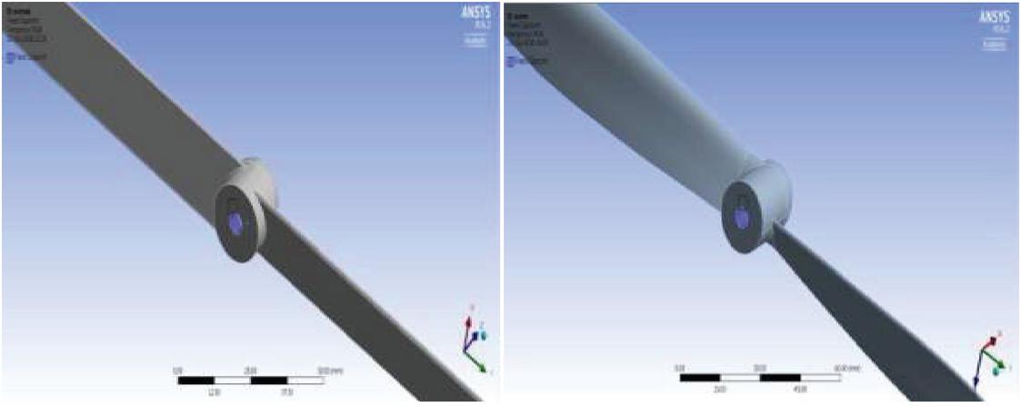
Figure 5 Fixed support boundary condition for Case A and B type propeller.
To analyzed the Quadcopter under vibration frequency two condition are used; with thrust force and without thrust force. The thrust force (F) can be calculated by following formula.
| (1) | |
| (2) |
Where m is the total mass (quadcopter plus payload) and g is acceleration due to gravity. K is the coefficients, depends upon propellers geometry and air density. If the value of m is 20 kg then the value of total thrust force.
Total Thrust force (F) mg 20*9.81 196.2 N
Thrust force required per propeller F/4 196.2/4 49.05 N
This thrust force is approximately 50 N for a single propeller. This thrust force is applied on both the propeller designs as shown in Figure 6. Carbon Fiber Reinforced Polymer (CFRP) material is used for simulation. CFRP is a lighter material which can be used in aerospace application with high strength. Table 1 shows the material properties of CFRP.
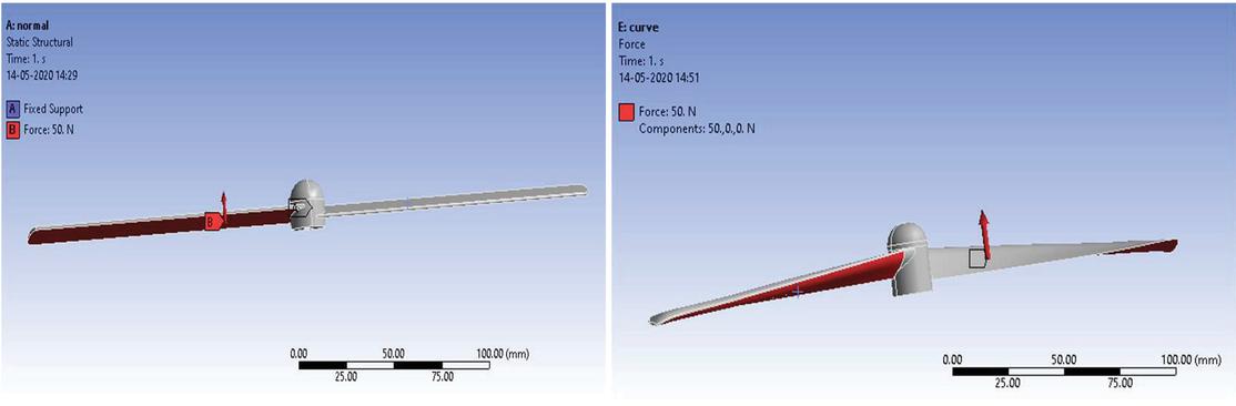
Figure 6 Applied thrust force boundary condition for Case A and B type propeller.
Table 1 CFRP material properties (Ahmad F. et al., 2019)
| Density | Youngs | Poission | Bulk | |
| Materials | (kg/m) | Modulus (MPa) | Ratio | Modulus (MPa) |
| CFRP | 1600 | 70000 | 0.3 | 58333 |
3 Simulation and Result
First, the two propeller designs (Case A and B) have been tested by applying thrust force in static structural module of Ansys workbench. Figures 7 and 8 show the total deformation due to applied thrust force. It is found that deformation is more in Case A as compared to Case B (Figure 9). Further, both the propeller designs have been tested for six modes of vibration without the application of thrust force as shown in Figures 10 and 12. After that the result of static structural has been imported to modal analysis module of Ansys to perform the pre-stress analysis. In pre-stress analysis, the stress generated in the static structural module is pre-applied to the propeller for modal analysis. Figures 11 and 13 show the frequency variation with the presence of thrust force i.e., pre-stressed condition.

Figure 7 Case A type propeller deformation.

Figure 8 Case B type propeller deformation.
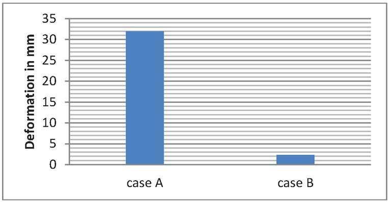
Figure 9 Total deformation comparison of both the propeller.
A. Vibration Frequency Variation for Case A Type Propeller
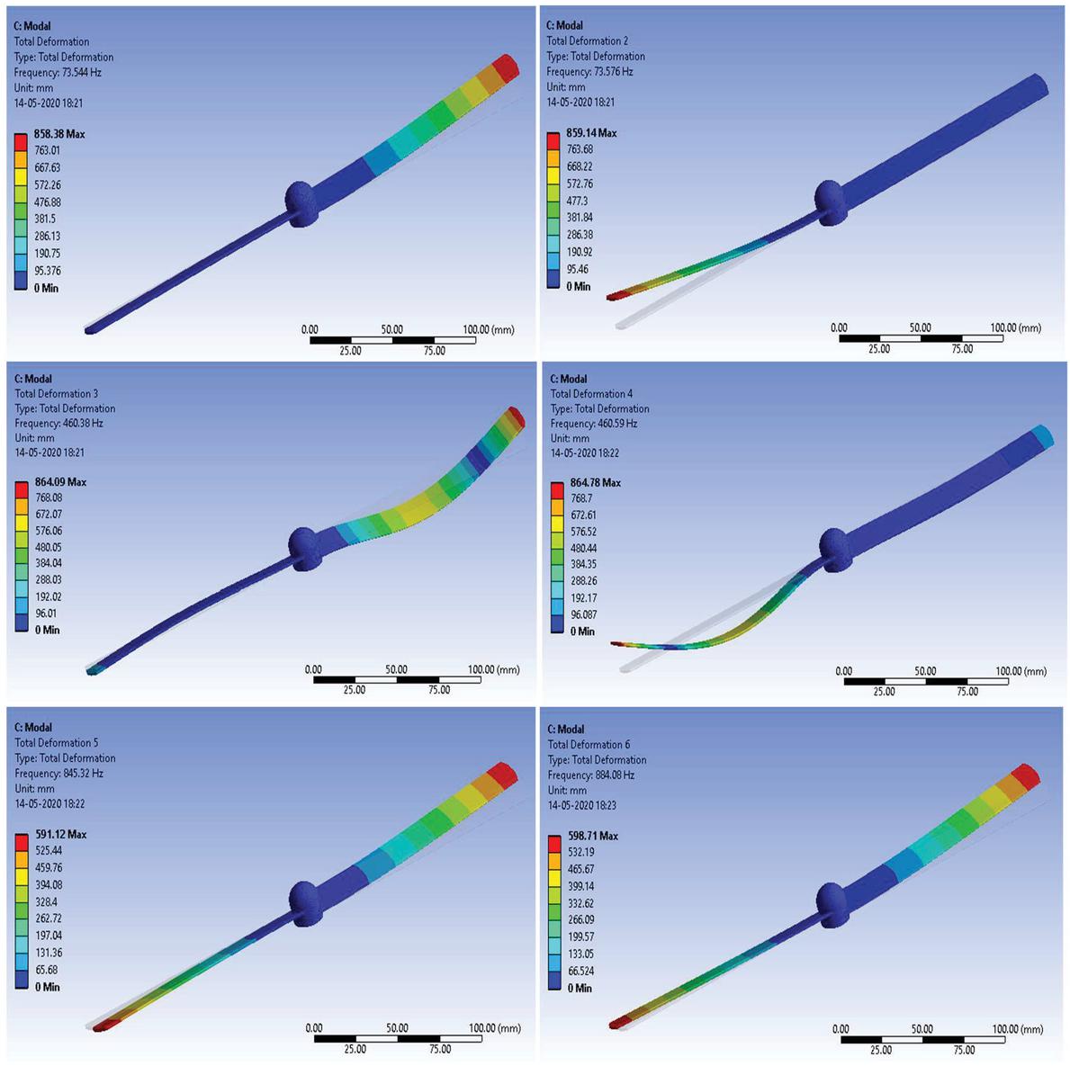
Figure 10 Vibration frequency variation without thrust force (Case A).
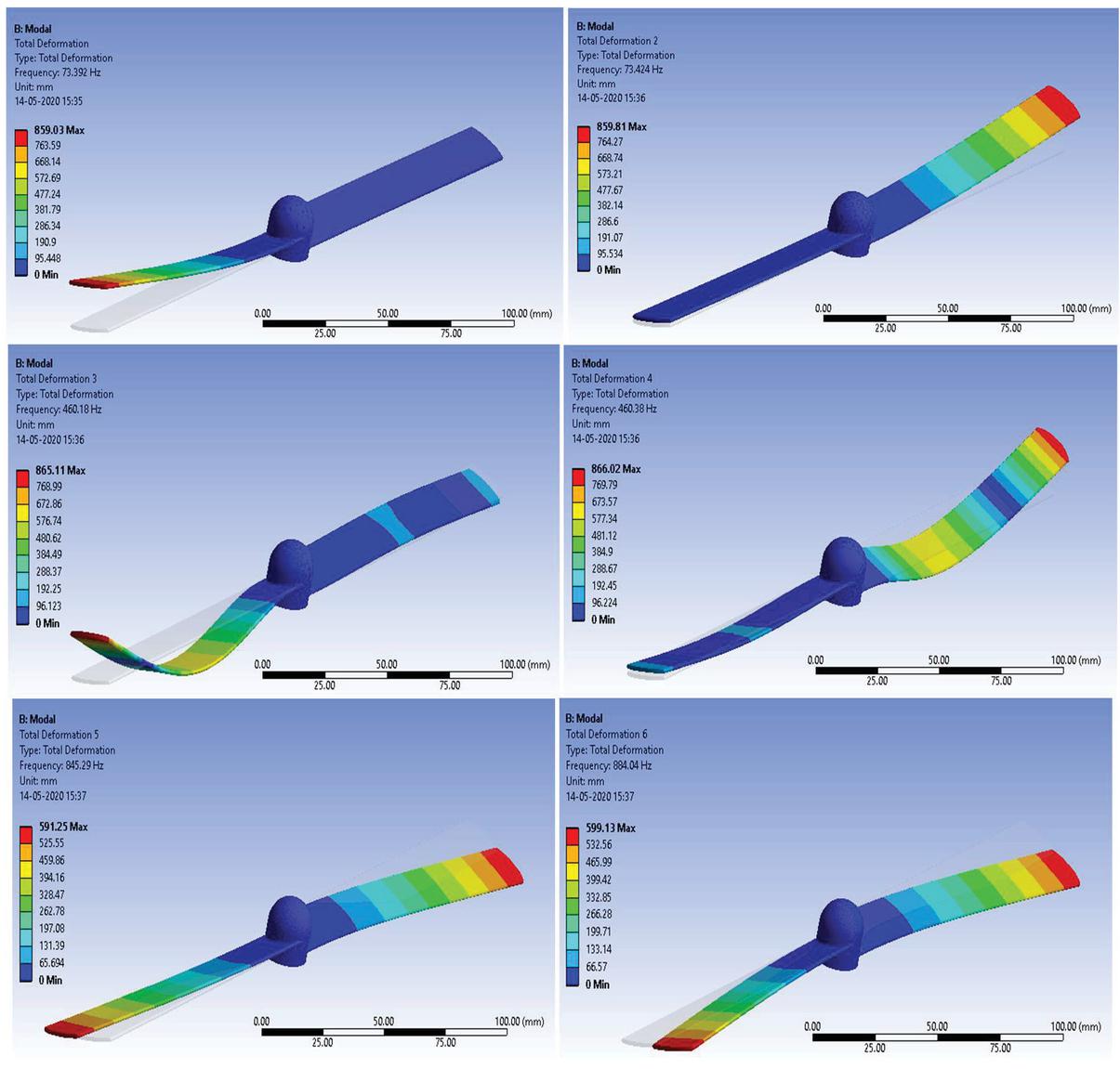
Figure 11 Vibration frequency variation with thrust force (Case A).
B. Vibration Frequency Variation for Case B Type Propeller
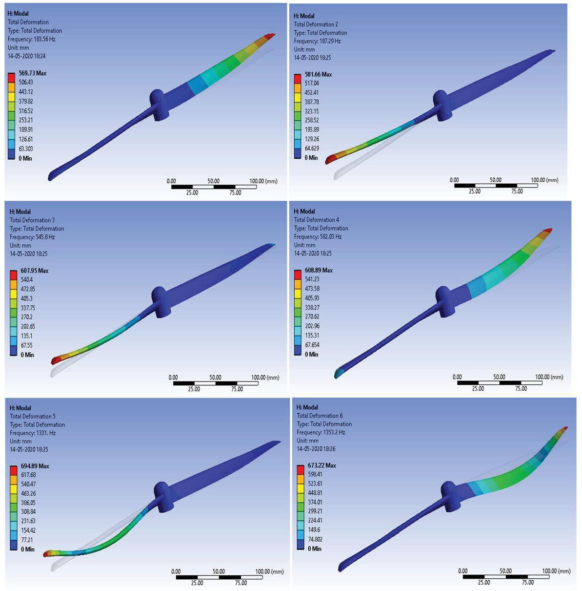
Figure 12 Vibration frequency variation without thrust force (Case B).
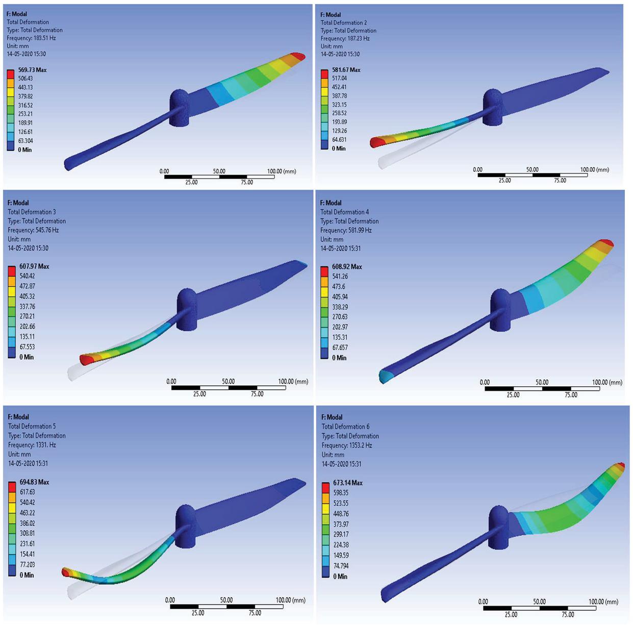
Figure 13 Vibration frequency variation with thrust force (Case B).
Table 2 Case A propeller frequency variation with or without thrust force
| Mode No. | Without Thrust | With Thrust |
| 1 | 73.544 | 73.392 |
| 2 | 73.576 | 73.424 |
| 3 | 460.38 | 460.18 |
| 4 | 460.59 | 460.38 |
| 5 | 845.32 | 845.29 |
| 6 | 884.08 | 884.04 |
The frequency ranges for the Case A and B propeller designs are given in Tables 2 and 3, respectively. Which are also plotted in Figures 14 and 15. It can be observed that for both the cases the frequency variation is negligible when analyzing with and without the thrust force. Thus, both the designs can sustain the thrust force.
Table 3 Case B propeller frequency variation with or without thrust force
| Mode No. | Without Thrust | With Thrust |
| 1 | 183.56 | 183.51 |
| 2 | 187.29 | 187.23 |
| 3 | 545.8 | 545.76 |
| 4 | 582.03 | 581.99 |
| 5 | 1331 | 1331 |
| 6 | 1353.2 | 1353.2 |
In Table 4 and Figure 16, frequency comparison is presented for Case A and B type propellers with pre-stressed condition (with thrust force). It is sufficient for comparison because there is not much difference without thrust force too. It can be seen that Case B type propeller shows the higher range of failure frequency (183.51 to 1353.20 Hz) than Case A type propeller (73.39 to 884.04 Hz). Hence, Case B propeller design is more reliable and strong under static and dynamic loading conditions.
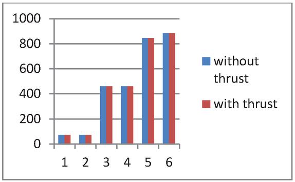
Figure 14 Frequency of Case A propeller.

Figure 15 Frequency of Case B propeller.
Table 4 Frequency values of Case A and B type propeller with thrust force
| Mode No. | Case A Type Propeller | Case B Type Propeller |
| 1 | 73.392 | 183.51 |
| 2 | 73.424 | 187.23 |
| 3 | 460.18 | 545.76 |
| 4 | 460.38 | 581.99 |
| 5 | 845.29 | 1331 |
| 6 | 884.04 | 1353.2 |

Figure 16 Frequency comparison of Case A and B type propeller with thrust force.

Figure 17 Validation of present result with past literature.
4 Conclusion
The CAD model of the Quadcopter’s propeller has been successfully created in Creo 2.0 design software and the first six vibration frequency have been calculated with or without the presence of thrust force. Two types of propeller designs are analyzed and compared for different mode shapes. The color contour graph guides the deformation rating under different frequencies and mode shapes. The red color shows the maximum and the blue shows the minimum deformation. Furthermore, the maximum deformation is found at the tip of the propeller which is under considerable limit. From tables and graphs, it can be concluded that case B type propeller has higher failure frequency (resonance frequency). Higher failure frequency make the design safe because to break the design external vibrational frequency need to match with the resonance frequency of that design. Furthermore the result is validated by (Ahmad F. et al., 2019) publish literature. Figure 17 conclude that, the propeller natural frequency is decrease by 15.98 Hz when performed the modal analysis with thrust force. The present study helps the researchers in finding out the resonance frequency of components under pre-stress conditions.
References
Ahmed, M. F., Zafar, M. N., & Mohanta, J. C. (2020, February). Modeling and Analysis of Quadcopter F450 Frame. In 2020 International Conference on Contemporary Computing and Applications (IC3A) (pp. 196–201). IEEE.
Ahmad, F., Bhandari, A., Kumar, P., & Patil, P. P. (2019, November). Modeling and Mechanical Vibration characteristics analysis of a Quadcopter Propeller using FEA. In IOP Conference Series: Materials Science and Engineering (Vol. 577, No. 1, p. 012022). IOP Publishing.
Ahmad, F., Kumar, P., & Patil, P. P. (2018). Modeling and simulation of a quadcopter with altitude and attitude control. Nonlinear Studies, 25(2).
Ahmed, F., Kumar, P., & Patil, P. P. (2016). Modeling and simulation of a quadcopter UAV. Nonlinear Studies, 23(4).
Gariya, N., Prasad, B., Panwar, V., & Kumar, P. (2020). Vibrational Analysis of Conducting Nanocomposite Actuator. Journal of Graphic Era University, 8(1), 42–48.
Kuantama, E., Craciun, D., Tarca, I., & Tarca, R. (2017). Quadcopter propeller design and performance analysis. In New Advances in Mechanisms, Mechanical Transmissions and Robotics (pp. 269–277). Springer, Cham.
Kumar, S., & Mishra, P. C. (2016). Finite element modeling for structural strength of quadcoptor type multi mode vehicle. Aerospace Science and Technology, 53, 252–266.
Martinetti, A., Margaryan, M., & van Dongen, L. (2018). Simulating mechanical stress on a micro Unmanned Aerial Vehicle (UAV) body frame for selecting maintenance actions. Procedia manufacturing, 16, 61–66.
Penkov, I., & Aleksandrov, D. (2017). Propeller shrouding influence on lift force of mini unmanned quadcopter. International Journal of Automotive and Mechanical Engineering, 14, 4486–4495.
Subudhi, C. S., & Ezhilarasi, D. (2018). Modeling and trajectory tracking with cascaded PD controller for quadrotor. Procedia computer science, 133, 952–959.
Singh, R., Kumar, R., Mishra, A., & Agarwal, A. (2020). Structural Analysis of Quadcopter Frame. Materials Today: Proceedings, 22, 3320–3329.
Xiu, H., Xu, T., Jones, A. H., Wei, G., & Ren, L. (2017, December). A reconfigurable quadcopter with foldable rotor arms and a deployable carrier. In 2017 IEEE International Conference on Robotics and Biomimetics (ROBIO) (pp. 1412–1417). IEEE.
Biographies

Faraz Ahmad pursuing his PhD in Mechanical Engineering. He received his master degree in CAD/CAM and Robotics from Graphic Era University, Dehradun. He was awarded by silver medal in his master degree. He has published 36 Research paper. He has been awarded with Excellent Research and Publication Award for the year 2020. His area of interest is Finite Element Analysis, Mechatronics, and CFD.

Pushpendra Kumar is working as an Associate Professor in the department of Mechanical Engineering at Graphic Era Deemed to be University, Dehradun, India. He received the Ph.D. degree in automatic control from the University of Lille, France in 2014. His research interests include Dynamics, Control, Robotics and Mechatronics.

Pravin P. Patil received M. Tech (Machine Design) and PhD (Mech. Engg.) degrees from the Indian Institute of Technology, Roorkee. He has published more than 100 research papers in highly indexed international journals and conferences. He is on reviewer panel of various reputed International Journals in his areas of research such as IEEE/ASME Transaction of Mechatronics, ISA transactions of Elsevier etc. He is consistently involved in teaching and research since last 21 years in multidisciplinary research areas which includes Finite Element Analysis, Mechatronics, Mechanical vibration, Soft Computing Techniques, Computational statistics techniques etc.
Journal of Graphic Era University, Vol. 9_2, 105–120.
doi: 10.13052/jgeu0975-1416.921
© 2021 River Publishers