Influence of Phi () Shaped in Circular Ring Inserts on Thermal Performance in Circular Tube Heat Exchanger: CFD Study
Gaurav Kandpal, Satyendra Singh*, Shubham Bisht and Himanshi Kharkwal
Department of Mechanical Engineering, Bipin Tripathi Kumaoun Institute of Technology, Dwarahat, Uttarakhand, India
E-mail: ssinghiitd@gmail.com
*Corresponding Author
Received 09 March 2022; Accepted 07 May 2022; Publication 04 March 2023
Abstract
Enhancement of heat exchangers with the usage of inserts which creates turbulence in fluid flow by enhancing heat transfer rate which is an appealing area for researchers to develop efficient and compact heat exchanger with low expenses. Present work deals with computational investigation on circular tube with shaped circular ring inserts taken as enhancer for better experience in heat transfer. The geometric dimensions of insert are 68 mm outer diameter with inner ring is half of outer diameter concentric ring having varying DR of 0.8, 0.85 and 0.9 with varying PR 3, 4 & 5 in which hydraulic diameter is 68.1 mm. The length of test section is 1500 mm with 1000 W/m of regular heat flux is applied and Re ranges from 3000 to 21000.
CFD analysis conducted, compared & results are presented where maximum augmentation of heat transfer could be obtained 5.02–11.21 times simultaneously TPF is 2.14–3.54 times as compared to smooth tube for inserts with DR 0.8 and PR 3 which attained maximum 3.07–5.1.
Keywords: Heat exchanger, thermal performance factor, CFD analysis.
Nomenclature
| f | Friction factor |
| Re | Reynolds number |
| Nu | Nusselt number |
| U | Velocity of air, (m/s) |
| D | Diameter of test tube, (m) |
| P | Pressure drop, (Pa) |
| Mass flow rate, (kg/s) | |
| T | Temperature (K) |
| I | Current, (A) |
| V | Voltage, (V) |
| Q | Heat transfer rate, (W) |
| L | Length of test section, (m) |
| Thermal performance factor, | |
| h | Heat transfer coefficient, (W/mK) |
| C | Specific heat capacity of hot air, (J/kgK) |
| k | Thermal conductivity of air, (W/mk) |
| Coefficient of discharge | |
| A | Heat transfer surface area, (m) |
| Velocity component in corresponding direction | |
| Rate of deformation of component | |
| Eddy viscosity | |
| Total entropy generation | |
| Greek Symbols: | |
| Density of air | |
| Dynamic viscosity of air | |
| Phase | |
| Range of orifice plate | |
| Subscript: | |
| i | Inlet |
| o | Outlet |
| s | Smooth tube |
| wm | Wall mean |
| fm | Fluid mean |
| Abbreviations | |
| CFD | Computational Fluid Domain |
| TPF | Thermal Performance Factor |
| DR | Diameter Ratio |
| PR | Pitch Ratio |
1 Introduction
Heat Exchanger is that system where is heat transfer takes place by the way of conduction, convection and negligible by radiation between two fluid flows which separated by using solid medium. Heat transfer rate enhanced by increment accomplished in surface area by making rough surface, putting limitations in path of flow and by giving distinct boundary situations which can be appropriate for device. So, here passive approach is best way from active, passive and compound method to approach enhance heat exchanger. Kumar et al. [1] checkout impact of solid circular disk tabulators experimentally and achieved enhancement in heat transfer is about 4.45 times when pitch ratio is 1 with diameter ratio 0.6 and TPF for pitch ratio 1 with 0.8 diameter ratio is 1.4 and minimum f for pitch ratio 4. In addition Kumar et al. [2] uses Circular Perforated Ring (CPR) insert, founds that 4 times augmentation in 8% perforation index with diameter ratio 0.8 where TPF enhance by 1.47 times in 24% perforation index with same diameter ratio and during experiment realizes that f is minimum for higher Re. Singh et al. [3] experimentally checkout Solid Ring Turbulator (SRT) with number of twisted tape gives swirl flow with higher Re. SRT roughened tube with quadruple co-twisted tape having highest TPF of 1.61 at pitch and twist ratio 1 and 2 respectively. Nu and f rises up with increment done in range of turns in co-twisted tape. Kumar et al. [4] inspect heat exchanger tube having protruded surface based on steam and span wise spacing, founds that 3.43 times enhancement in heat transfer and 2.31 times enhancement in TPF at 10, 10 steam and span wise spacing respectively. Nu increases with increase in Re, steam wise spacing and span wise spacing. f decreases with increase in steam wise spacing and with decrease in span wise spacing. Bhuiya et al. [5] experimentally investigate tube equipped with twisted tape inserts which is double counter and placed in a tube and performed at twist ratios and founds that Nu, f and thermal enhancement efficiency increases with decreasing twist ratio and achieved maximum thermal enhancement of 1.34. Eiamsa-ard et al. [6] experimentally uses Circular Ring Turbulator (CRT) and Twisted Tape (TT) inserts as swirl generator in heat exchanger on assumed twist ratios for CRT () and TT (y/w) and found that highest TPF for combined CRT and TT is 1.42 at 1, y/w 3. Also, heat transfer rate, f for blended CRT and TT are higher than CRT alone. Matani et al. [7] uses twisted tape with wire coils, Twisted tape used as swirl flow generator even as wire coil with twisted tape used as co-swirl generator. Test conducted on distinct twist ratios (y/w) in twisted tape with different wire coil pitch ratio. The result indicates f, TPF will increases with increase in twist ratio. Wire coil with twisted tape is more efficient in enhancement of heat transfer also concluded that swirl flow is effective in heat exchanger. Promvonge et al. [8] experimentally examine twisted tape with wire coil turbulators in circular tube and twisted tape as continuous swirl flow generator. Result reveals that wire coil used with twisted tape allows two times increment in heat transfer than wire coil as well as twisted tape alone. Combined twisted tape with wire coil at smallest twist and pitch ratio gives better heat transfer and causes high pressure drop. Gautam et al. [9] experimentally look at triple wing insert vortex generator among circular tube using parameters like twist ratio & porosity and founds that increase in twist ratio decreases Nu, f and TPF. However porosity decreases Nu increases and relatively enhancement in f is seen and TPF for lower Re is maximum. Gunes et al. [10] in his experimentally investigate coiled wire with cross sectioned shape as equilateral triangle insert in a tube inserts at exclusive pitch ratios with distinctive triangle length & duration, examined that coiled wire will increase heat transfer and pressure drop. Additionally, Nu increases with decrease in pitch ratio. In his result highest overall efficiency achieved by him is 36.5% at pitch ratio 1 in comparison with smooth tube. Result exhibits that use of thin wire with huge coil pitch ratio is not thermodynamically advantageous for high Re. Promvonnge et al. [11] checkout experimentally on tube fitted with inclined vortex ring at in heat exchanger with exclusive ring width ratio and ring pitch ratio at exclusive Re. This forms of insert used to create counter rotating vortices for the duration of flow to growth in turbulence. With larger width ratio better heat transfer and pressure loss are seen and with pitch ratio the opposite trend is seen. At width ratio 0.1, pitch ratio 0.5 maximum heat transfer of 1.4 is analysed. Kongkaitpaiboon et al. [12] experimentally look at convective heat transfer and pressure loss in tube fitted with Circular Ring Tabulator’s (CRT) with numerous geometries at different pitch and diameter ratio, CRT outcomes better heat transfer rate and larger pressure drop at smallest pitch and diameter ratio. Maximum TPF of 1.07 is found to be at 0.7, 6 diameter and pitch ratio respectively. Eiamsa-ard et al. [13] experimentally look into correlation among different parameters in non-uniform wire coil and twisted tape insert, and founds that maximum TPF in DI-coil (Decreasing/ increasing coil pitch ratio) at lower Re is 1.25. Eiamsa-ard et al. [14] experimentally investigate enhance heat transfer and pressure loss with the insertion of twisted tape with different twist and space ratios and observes that if twist ratio decreases than Nu and f will increases and with increase in space ratio the heat transfer rate is decreasing and conclude that full length dual twisted tape having better enchancement performance. Bas et al. [15] experimentally looks into heat transfer enhancement in tube with twisted tape insert with different parameters as twist ratio’s and clearance ratio’s, observes that increase in Nu when twist ratio and clearance ratio is increasing concurrently with increase in Re. Maximum TPF is 1.756 visible at 0.0178, 2 clearance and twist ratio respectively. In this he examine enhancement is also achieved during disjoin twisted tape from tube wall. Zohir et al. [16] experimentally noticed heat transfer and pressure drop in sudden expansion in pipe with different swirl angles at different position’s, this indicates putting propeller upstream improves heat transfer rate and maximum at where downstream offers enhancement factor. Chamoli et al. [17] experimentally inspect analysis (Taughi grey relational) to optimize flow and geometric parameters in perforated disk insert equipped with heat exchanger tube and founds that it is effective in optimising which work out in heat transfer enhancement. Promvonge et al. [18] experimentally studied effect of circular tube fitted with conical nozzle turbulators inserts in heat exchanger with various pitch ratios. As increment in Re increases Nu this enhance heat transfer coefficient. f will increases when reduction in pitch ratio is accomplished. Eiamsa-ard et al. [19] look at experimentally on V-Nozzle turbulators inserts and founds that heat transfer rate increased by 270% and maximum TPF (1.19) is at smallest pitch ratio. Eiamsa-ard et al. [20] experimentally and numerically look at in double sided Delta-wing Tape insert with Alternate-Axes with different parameters as wing-width ratio and wing-pitch ratio and founds that T-WA (T-W with alternate axis) has better heat transfer rate and f than T-W (straight tape with double sided Delta-wing). Pandey et al. [21] studied effect of Y shaped insert extruded in full length of test section with unique perforation index (0%, 10%, 20%, & 30%) on wings, for 3000–21000 Re and founds minimal f is at lower perforation index and give maximum TPF and heat transfer rate over smooth tube is 2.88 & 5.05 that is at 0% perforation index case.
It may be analysed from the literature survey that during theoretical evaluation of circular tube heat exchanger disturbance both core or surface of fluid flow are taken into the consideration to increase overall thermal performance of the system. So, here shaped in circular ring insert used which creates core disturbance in order to get high heat transfer rate.
2 Physical Model
The test segment tube is having 68.1 mm hydraulic diameter with length 1500 mm tube test segment, air as operating fluid and insert is used as shaped in circular ring insert with 68 mm outer diameter ring with concentric ring and its inner ring outer diameter is half of outer ring outer diameter, with DR (0.8, 0.85 & 0.9) and thickness of strip is identical to internal ring thickness and analysed for PR (3, 4 & 5) with insert are extruded to 1 mm, the insert with test segment and insert is shown in Figure 1.
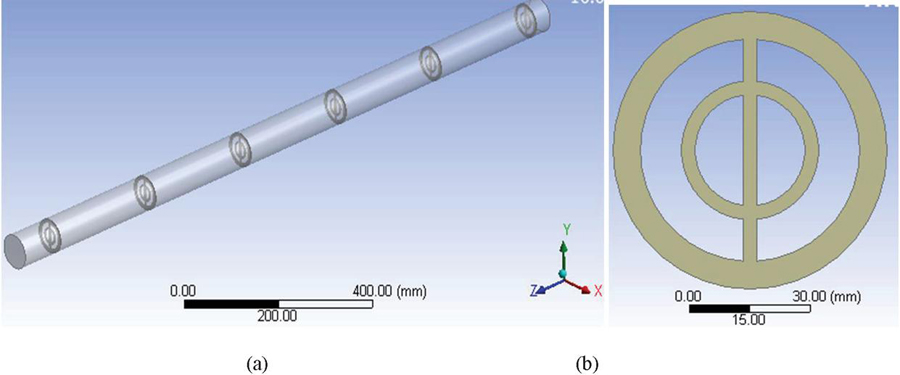
Figure 1 (a) Inserts placed in pipe. (b) Front view of insert.
The formulae’s used are:
Reynolds number,
| (1) |
Nusselt number,
| (2) |
Prandtl number,
| (3) |
Mass flow rate,
| (4) |
Wall mean temperature,
| (5) |
Fluid mean temperature,
| (6) |
Heat transfer coefficient,
| (7) |
Friction factor,
| (8) |
Thermal performance factor,
| (9) |
For duration of analysis inlet temperature of working fluid is 300 K with properties as density (1.225 kg/m), specific heat (1006.4 J/kgK), thermal conductivity (0.0242 W/mK) and dynamic viscosity (1.7894 10 kg/ms) with steady heat flux 1000 W/m.
3 Mathematical Model
The fluid considered as incompressible throughout flow and pipe is insulated this implies transfer by radiation of thermal energy is zero.
Right here Governing equations are taken from Pandey et al. [21];
Continuity equation,
| (10) |
Momentum equation,
| (11) |
Energy Equation,
| (12) |
Formulae used by Parameters,
Diameter Ratio (DR),
| (13) |
Where, inner and outer diameter which are chosen are of identical ring.
Pitch ratio,
| (14) |
Turbulence models;
This is two equation models that describe turbulence in two shipping equation (turbulence kinetic energy (k) & dissipiation rate of kinetic energy ()). There is standard turbulence model is used.
Turbulence kinetic energy (k),
| (15) |
For Dissipate kinetic energy ,
| (16) |
are adjustable constant.
Where values of adjustable constant are
Total entropy generation ():
It is the sum of entropy generation due to thermal factor and frictional factor.
Mathematically,
So, total entropy generation [22],
| (17) |
4 Boundary Conditions
Ansys 19.1 fluent module is used to computational study for present work in this the standard k- turbulence model with finite element method is used in numerical evaluation and regular heat flux of 1000 W/m is supplied to surface of pipe with inlet temperature of 300 K and velocity given at inlet from 0.741 to 5.14 m/s according to range of Re 3000 to 21000 respectively.
Table 1 Meshing parameters and conditions
| Meshing parameters | Conditions |
| Use advanced size function | On: Proximity & Curvature |
| Relevance center | fine |
| Smoothing | Medium |
| Growth rate | 1.2 |
| Transition ratio | 0.272 |
| Maximum layer | 5 |
| Method | Cut-shell |
| Element | 24,635 |
The parameters used in Ansys 19.1 meshing are shown in above Table 1 that is taken when GIT gives minimum variation at 24,635 elements as shown in Table 2 for shaped in circular ring inserts inside circular tube heat exchanger.
Table 2 Grit independence test (GIT)
| Grit Number | Nu | |
| 12049 | 140.02 | |
| 24635 | 143.33 | 0.0231 |
| 55965 | 146.75 | 0.0233 |
5 Result and Discussion
5.1 Computational Results
The reading taken from computational statistics having consequences among them are shown below:
5.1.1 Effect on heat transfer
The aim of this evaluation is to enhance the heat transfer rate as compared to the plain tube (smooth tube) heat exchanger or the tube without any inserts geometry.
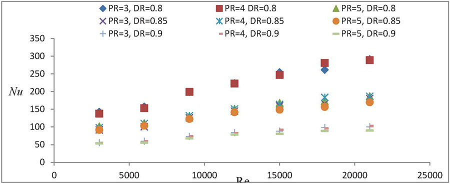
Figure 2 Variation of Nusselt Number with Reynolds Number for shaped ring inserts.
Figure 2 display that with increment in Re there is concurrently increase in Nu which increases heat transfer. When decrement in PR & DR that increases Nu since heat transfer enhances through examine that the value of Nu is maximum at DR 0.8 with PR 3 is 292.
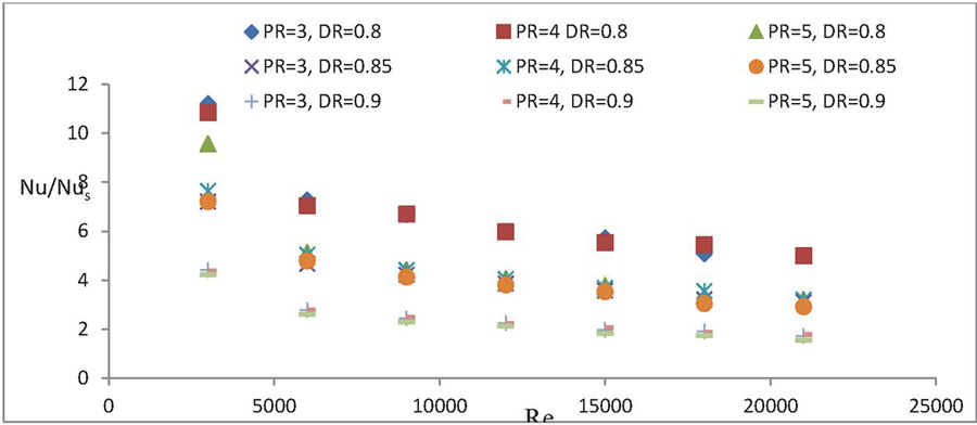
Figure 3 Variation of Nu/Nu with Reynolds Number for shaped ring insert.
Figure 3 indicates the variation of Nu/Nu with Re, Nu/Nu is reducing with increasing Re. It can clearly seen with graph that as DR increases then ratio of Nu/Nu decreases simultaneously and also decreases with increasing PR.
5.1.2 Effect on friction factor
For the better thermal performance of the heat exchanger, f have to be as low as possible, f is inversely proportional to thermal performance. It can be observed in Figure 4 which suggests as increment in Re, f slightly reduces and is minimum at higher Re. It may be seen from figure that as PR & DR values are reduces than f also reduces and is minimum at PR 3 with DR 0.85.
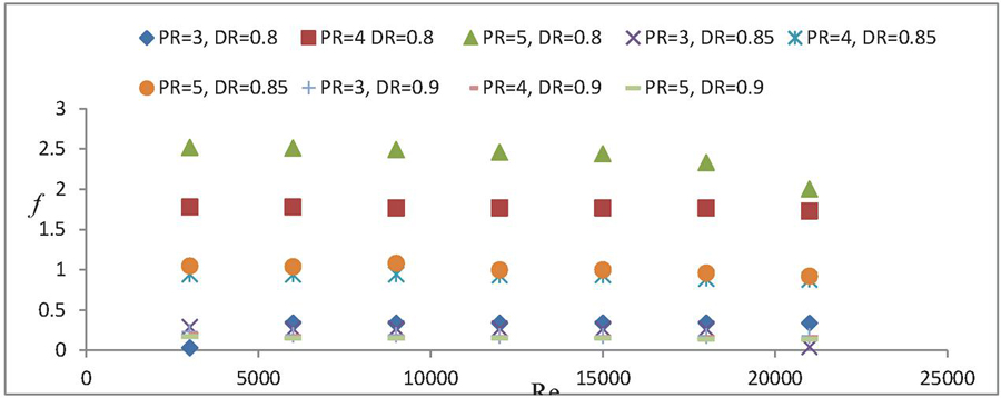
Figure 4 Variation of Friction factor with Reynolds Number for shaped ring insert.
Friction ratio (f/fs) shows the ratio of enhancement in f when inserts are located in test section to when the tube is smooth (no inserts) in test section. It has been observed that minimum value of f/fs 1.61 times is found at DR 0.85 with PR 3, as compared to the plain tube heat exchanger. Figure 5 represents the increase in f/f with increasing Re for shaped in circular ring inserts as compared to that of smooth tube. With increasing PR the f/f ratio also increases and reducing with increase in DR.
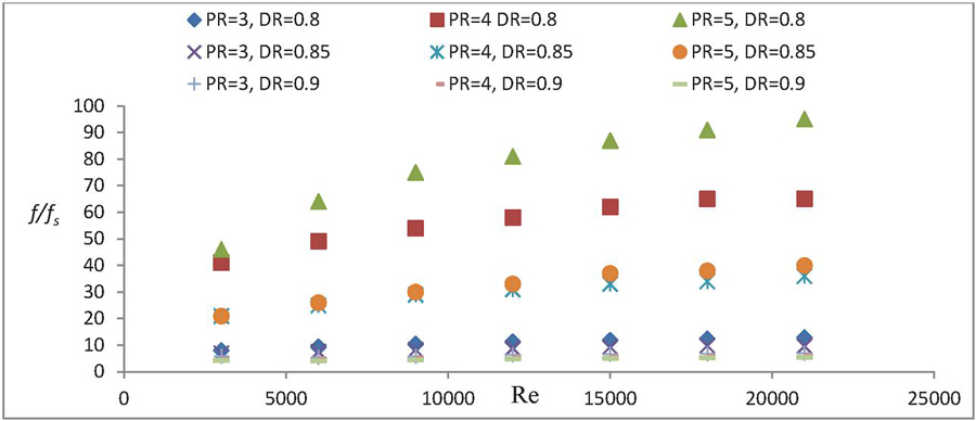
Figure 5 Variation of f/f with Reynolds Number for shaped ring insert.
5.1.3 Effect on thermal performance
Thermal performance of heat exchanger relies mainly upon on two factors Nu/Nu and f/f. To obtain superior effect, it is necessary to use that type of geometry having that’s TPF is greater than 1. So, shaped in circular ring insert is such type of insert gave the thermal performance of 3.54 with PR 3 and DR 0.8.
Variation of TPF with Re is shown in Figure 6. It is observed that the TPF is better at lower range of Re and as the value of Re increases the value of TPF decreases. As visible in graph that by reducing PR this consequences increment in TPF and reduces with increasing DR.
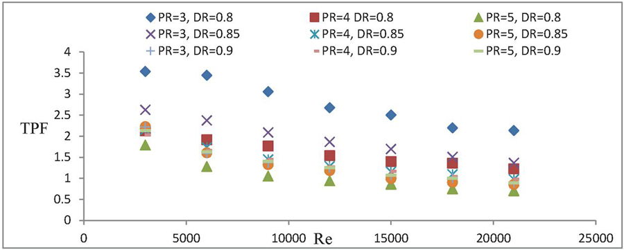
Figure 6 Variation of TPF with Reynolds Number for shaped ring insert.
5.1.4 Effect on total entropy generation
is mainly depend on inlet, outlet temperature and pressure difference. is decreasing with increasing Re So, irrevesibility of the system decreases with increasing Re which shows that randomness of the system decreases and with increasing DR will be decreasing and changes slightly with PR’s. varied from 5.1–1.4 in the whole analysis as shown in Figure 7 as DR, PR.
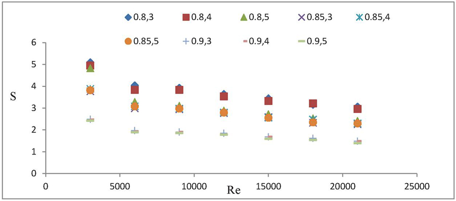
Figure 7 Variation of Total Entropy Generation with Reynolds Number for shaped in ring insert.
5.2 Comparison with Previous Work
The present CFD analysis, maximum TPF is compared with formerly published papers of Bhuiya et al. (2014), Eiamsa-ard et al. (2013), Matani et al. (2013), Bas et al. (2012), uses double counter twisted tape inserts, circular-rings and twisted tapes, twisted tapes and wire coils, twisted tape inserts placed separately from the tube wall respectively with present work shaped in circular ring inserts and comparison shows as in Figure 8 and graph indicates that maximum TPF is attained at present work with respect to preceding work done on inserts.

Figure 8 Comparison of previous work TPF with Re to present work.
6 Conclusion
Flow parameters in a fluid flow shows principal impact on heat transfer, f and TPF.
• With taking different PR’s heat transfer slightly varies for all set of insert geometries
• In present work the Nu increases with increasing Re and with deceasing PR & DR.
• Nu/Nu ratio and f both decreases with increasing all (Re, PR & DR).
• f/fs ratio slightly increases with Re, f/fs ratio increases with increment in PR and reducing with DR increment.
• TPF decreases with increasing Re, TPF increases with increasing PR & decreases with increasing DR. Augmentation decreases with PR & DR. Augmentation decreases with increasing Re.
• is decreasing with increasing Re and DR. and changes slightly with PR’s.
References
[1] Kumar, A., Chamoli, S. and Kumar, M., 2016. Experimental investigation on thermal performance and fluid flow characteristics in heat exchanger tube with solid hollow circular disk inserts. Applied Thermal Engineering, 100, pp. 227–236.
[2] Kumar, A., Chamoli, S., Kumar, M. and Singh, S., 2016. Experimental investigation on thermal performance and fluid flow characteristics in circular cylindrical tube with circular perforated ring inserts. Experimental Thermal and Fluid Science, 79, pp. 168–174.
[3] Singh, V., Chamoli, S., Kumar, M. and Kumar, A., 2016. Heat transfer and fluid flow characteristics of heat exchanger tube with multiple twisted tapes and solid rings inserts. Chemical Engineering and Processing: Process Intensification, 102, pp. 156–168.
[4] Kumar, P., Kumar, A., Chamoli, S. and Kumar, M., 2016. Experimental investigation of heat transfer enhancement and fluid flow characteristics in a protruded surface heat exchanger tube. Experimental Thermal and Fluid Science, 71, pp. 42–51.
[5] Bhuiya, M.M.K., Sayem, A.S.M., Islam, M., Chowdhury, M.S.U. and Shahabuddin, M., 2014. Performance assessment in a heat exchanger tube fitted with double counter twisted tape inserts. International Communications in Heat and Mass Transfer, 50, pp. 25–33.
[6] Eiamsa-ard, S., Kongkaitpaiboon, V. and Nanan, K., 2013. Thermohydraulics of turbulent flow through heat exchanger tubes fitted with circular-rings and twisted tapes. Chinese Journal of Chemical Engineering, 21(6), pp. 585–593.
[7] Matani, D.A. and Dahake, S.A., 2013. Experimental study of heat transfer enhancement in a pipe using twisted tapes and wire coils. International Journal of Mechanical Engineering & Technology (IJMET), 4(2), pp. 100–111.
[8] Promvonge, P., 2008. Thermal augmentation in circular tube with twisted tape and wire coil turbulators. Energy Conversion and Management, 49(11), pp. 2949–2955.
[9] Gautam, A., Pandey, L. and Singh, S., 2018. Influence of perforated triple wing vortex generator on a turbulent flow through a circular tube. Heat and Mass Transfer, 54(7), pp. 2009–2021.
[10] Gunes, S., Ozceyhan, V. and Buyukalaca, O., 2010. Heat transfer enhancement in a tube with equilateral triangle cross sectioned coiled wire inserts. Experimental Thermal and Fluid Science, 34(6), pp. 684–691.
[11] Promvonge, P., Koolnapadol, N., Pimsarn, M. and Thianpong, C., 2014. Thermal performance enhancement in a heat exchanger tube fitted with inclined vortex rings. Applied Thermal Engineering, 62(1), pp. 285–292.
[12] Kongkaitpaiboon, V., Nanan, K. and Eiamsa-Ard, S., 2010. Experimental investigation of convective heat transfer and pressure loss in a round tube fitted with circular-ring turbulators. International Communications in Heat and Mass Transfer, 37(5), pp. 568–574.
[13] Eiamsa-Ard, S., Nivesrangsan, P., Chokphoemphun, S. and Promvonge, P., 2010. Influence of combined non-uniform wire coil and twisted tape inserts on thermal performance characteristics. International Communications in Heat and Mass Transfer, 37(7), pp. 850–856.
[14] Ghadirijafarbeigloo, S., Zamzamian, A.H. and Yaghoubi, M., 2014. 3-D numerical simulation of heat transfer and turbulent flow in a receiver tube of solar parabolic trough concentrator with louvered twisted-tape inserts. Energy procedia, 49, pp. 373–380.
[15] Bas, H. and Ozceyhan, V., 2012. Heat transfer enhancement in a tube with twisted tape inserts placed separately from the tube wall. Experimental Thermal and Fluid Science, 41, pp. 51–58.
[16] Zohir, A.E. and Gomaa, A.G., 2013. Heat transfer enhancement through sudden expansion pipe airflow using swirl generator with different angles. Experimental thermal and fluid science, 45, pp. 146–154.
[17] Chamoli, S., Yu, P. and Kumar, A., 2016. Multi-response optimization of geometric and flow parameters in a heat exchanger tube with perforated disk inserts by Taguchi grey relational analysis. Applied Thermal Engineering, 103, pp. 1339–1350.
[18] Promvonge, P. and Eiamsa-ard, S., 2007. Heat transfer and turbulent flow friction in a circular tube fitted with conical-nozzle turbulators. International Communications in Heat and Mass Transfer, 34(1), pp. 72–82.
[19] Eiamsa-ard, S. and Promvonge, P., 2006. Experimental investigation of heat transfer and friction characteristics in a circular tube fitted with V-nozzle turbulators. International Communications in Heat and Mass Transfer, 33(5), pp. 591–600.
[20] Eiamsa-Ard, S. and Promvonge, P., 2011. Influence of double-sided delta-wing tape insert with alternate-axes on flow and heat transfer characteristics in a heat exchanger tube. Chinese Journal of Chemical Engineering, 19(3), pp. 410–423.
[21] Pandey L., Prajapati H., Singh S. CFD study for enhancement of heat transfer and flow characteristics of circular tube heat exchanger using Y-shaped insert. Materials Today: Proceedings. 2020 Dec. 11.
[22] Cao, Y., Ayed, H., Dizaji, H.S., Hashemian, M. and Wae-hayee, M., 2021. Entropic analysis of a double helical tube heat exchanger including circular depressions on both inner and outer tube. Case Studies in Thermal Engineering, 26, p. 101053.
Biographies

Gaurav Kandpal is a M.Tech scholar in the Mechanical Engineering Department of B.T. Kumaon Institute of Technology, Dwaraht, India. His research interests includes heat and mass transfer enhancement and mass transfer enhancement.

Satyendra Singh is a Professor at BTKIT, Dwarahat, India. He received his Ph.D. from IIT Delhi, India. He has research interest in finite element analysis, pressure vessels and piping, plates and shells, composite structures and passive method of heat transfer enhancement and solar thermal thermal analysis. He is life member of Indian society of Technical Education and Fellow of Institution of Engineers (India). He has more than one fifty publications in international and national journals and conferences.

Shubham Bisht is a M.Tech scholar in the Mechanical Engineering Department of B.T. Kumaon Institute of Technology, Dwaraht, India. His research interests includes heat and mass transfer enhancement and mass transfer enhancement.

Himanshi Kharkwal is an Assistant Professor in the Department of Mechanical Engineering, SLSET, Kitchha, India. She received M.Tech degree from BTKIT Dwaraht. Her research area includes passive method of heat transfer enhancement and solar thermal.
Journal of Graphic Era University, Vol. 11_1, 85–102.
doi: 10.13052/jgeu0975-1416.1117
© 2023 River Publishers